In-Service OTDR Monitoring and Mitigating the Effects of Raman Scattering
Today’s high-capacity communication networks depend on optical fiber to transport huge amounts of internet, data, and video traffic. Damaged or broken fibers not only disrupt thousands of users, but can threaten the operation of critical infrastructures. It is therefore essential to have a fiber network that is highly available and reliable.
Furthermore, a single fiber link can generate significant revenue for a service provider, so any failure demands immediate response to restore service. Instead of traditional, time-consuming field test practices to isolate and identify faults, integrated network monitoring with targeted action ensures the fastest restoration and highest service availability.
Remote fiber test or monitoring systems
Fiber monitoring solutions have proven to be the fastest, most efficient tool to identify and locate link outages. The ability to proactively detect fiber degradation at an early stage and pinpoint fiber faults precisely from a central location helps service providers meet customer expectations for fiber-optic network availability and maintaining quality of service (QoS) and service-level agreements (SLAs).
Since individual fibers can be prone to damage or degradation, it is becoming more common practice to monitor all the fibers in a cable, whether dark or live (lit). Live fiber or in-service monitoring, which by design does not disrupt network traffic or adversely affect customer experience, is gaining popularity since this provides a dynamic evaluation of network performance. Such monitoring also can be tied to other system alarms or network probes that provide additional triggering capabilities.
Out-of-service testing versus in-service fiber monitoring
During installation and commissioning, optical fibers are usually tested with a field-portable optical time-domain reflectometer (OTDR) operating at the same wavelength(s) as the traffic signals the fiber will transport. This industry-accepted practice verifies the fibers propagate signals according to known attenuation characteristics and that fusion splices and connections are within accepted limits. Since the fibers are not in service or are “dark,” there are no traffic signals to consider or interfere with. Similarly, dark fiber monitoring can also be referred to or classified as out-of-service testing.
In-service or live fiber testing by definition uses an out-of-band wavelength and requires a filtered wave-division multiplexer (FWDM) to combine the OTDR test signal and traffic signal into a single fiber. The FWDM not only combines the OTDR’s signal into the fiber under test, but it also filters and directs the backscattered signal back to the OTDR for processing. Likewise, the FWDM also prevents the OTDR signal from reaching the transmission equipment.
In May 2000, the ITU-T L.41 recommendation identified both 1625-nm and 1650-nm wavelengths for in-service maintenance of transmission networks operating at 1310-nm or 1550-nm spectrum. This recommendation was renumbered to L.301 in February 2016 without modification and remains in force today. With the advent of DWDM technology, the ITU-T in parallel created the G.697 recommendation in June 2004 to focus on the optical monitoring aspects for optical signals implementing bit rates up to 10 Gbps using non-return to zero (NRZ) or return to zero (RZ) line coding, as well as bit rates up to 40 and 100 Gbps using advanced modulation formats.
Generally speaking, 1625 nm is the preferred wavelength for monitoring legacy 1310/1550-nm systems, largely due to laser cost. The 1650-nm wavelength is recommended for CWDM, DWDM, XGS-PON, and TWDM-PON systems where the traffic wavelengths extend into the L-Band.
Nonlinear effects in optical fibers
In-service testing on C-Band transmission systems employing OTDR technology at 1625-nm or 1650-nm wavelengths requires an understanding of nonlinearity effects in fibers. Nonlinear effects are caused when the incident optical power of a fiber exceeds a certain value, triggering the nonlinear polarization of fiber materials. This nonlinear effect is proportional to the optical power density of the signals, so in a DWDM system where a single fiber transports multiple optical channels, this composite high power level produces the nonlinearity effect in the fiber. Nonlinearity becomes a key factor that limits transmission performance if not managed properly.
Figure 1 illustrates the major nonlinearities in optical fibers.
Figure 1. Non-linear effects in optical fiber.
Raman effects and in-service fiber monitoring
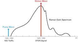
Of all the nonlinear effects identified in Figure 1, stimulated Raman scattering (SRS) is of biggest concern for in-service monitoring applications. In brief terms, SRS is an interaction between the incident wave (also known as the pump wave) and of the new frequency-shifted wave (also known as the Stokes wave). SRS causes depletion of the shorter (pump) wavelength and amplification of the longer (Stokes) wavelength. The Raman gain peak occurs when the Stokes frequency is about 13 THz (~100 nm) away from the pump’s frequency, and this falls directly within the OTDR test wavelength spectrum (see Figure 2). If the power of the shorter wavelength signal is less than the SRS threshold then spontaneous Raman scattering (SpRS) occurs with the same spectral properties.
In other words, when the 1550-nm C-band traffic signal propagates along the fiber, the backscattered signal related to the Stokes component coincides with the OTDR’s 1625/1650-nm test signal and passes through the OTDR’s filtered test port almost without loss. Despite the Raman scattering power level being quite small, the OTDR’s sensitivity is very high, and this scattering can significantly reduce the OTDR’s dynamic range.
Figure 2. Raman gain spectrum.
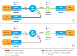
The locations of the OTDR, including the transmitter (Tx) and receiver (Rx) of the communication equipment, are shown in Figure 3. In this example, the OTDR signal at 1625 nm and the traffic signal at 1550 nm can propagate in the same or opposite direction; the backscatter from the Stokes wave or scattered Raman radiation returns to the OTDR.
Figure 3. OTDR and communication equipment locations. In A) the OTDR and Tx are at the same end of the fiber link; in B) the OTDR and Tx are at the opposite ends of the fiber link.
What is the optimal OTDR location for in-service monitoring?
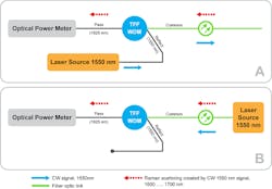
The question of where the best place to install the in-service monitoring OTDR for optimal performance often arises. To answer this question, the Raman scattering power from the Stokes wave was measured in an example system. It should be noted that measurements were conducted with a CW laser source, but traffic signals with modulation will deliver slightly different results. The measurement schemes are depicted in Figure 4.
Figure 4. Measurement of the back (a) and forward (b) Raman scattering.
Test procedure
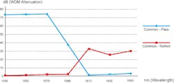
A thin-film filter (TFF) WDM was used to filter out the Raman scattering from the total radiation propagating in the fiber link. The insertion loss and isolation of the WDM were measured with CWDM and 1625- and 1650-nm lasers (see Figure 5). For more precise isolation measurements, the laser spectrum was previously cut with CWDM and appropriate TFF multiplexers.
Figure 5. Raman scattering through TFF WDM.
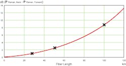
The 1550-nm laser source with a power level of 0 dBm simulated the traffic communication signal. The broadband optical power meter measured the optical power received by the OTDR port of the WDM filter. The difference between the back and forward Raman scattering power was calculated based on the fiber length.
Figure 6 plots the ratio of spontaneous Raman scattering versus fiber length, where fiber attenuation was assumed to be 0.19 dB/km. The results of the different length measurements for 25, 50, and 100 km are indicated.
Figure 6. Ratio of Raman power (back and forward) and fiber length.
Conclusion
Based on these results, it can be concluded that at the OTDR input, the Raman backscattered power is higher than the forward scattered power. Therefore, to minimize Raman interference, the OTDR and the transmitter of the communication equipment should ideally be located at opposite ends of the fiber link.
However, there are a few caveats:
- This case study excludes situations where Raman amplifiers and EDFAs may be deployed together on the same fiber link.
- Traffic signal was simulated at 1550 nm, but it should be noted that multiple DWDM signals across the entire C-Band, for example, will produce slightly different results.
- Fiber length is not only the criterion for the generation of SpRS. The intensity of the optical signal, the effective area of the fiber, and other parameters will influence the measurement.
References
- ITU-T L.41/301: Maintenance wavelength on fibres carrying signals.
- ITU-T Supplement G.42: Guide on the use of the ITU-T Recommendations related to optical fibres and systems technology.
- ITU-T G.697: Optical monitoring for dense wavelength division multiplexing systems.
- IEC TR 61282-4:2013: Fibre optic communication system design guides - Part 4: Accommodation and utilization of non-linear effects.
- Non-Linear Scattering Effects in Optical Fibers, S. P. Singh, R. Gangwar, and N. Singh.
- “Refraction and Scattering: What They Do to Field Transmission Systems”, Tutorial, Optical Fiber Conference (OFC 2002), Anaheim, USA, 18 Mar. 2002, by Andre Girard.
- Chraplyvy, J. Lightwave Technology, Oct. 1990, p. 1549.
Michael Grinstein ischief engineer and head of metrology at VeEX Optixsoft Division. He has been developing fiber-optic instruments and related test methods since 1990. Prior to joining the VeEX Optixsoft Division in 2014, he worked at the Institute of Information Technologies (IIT), which was the first company in the former Soviet Union to develop and build OTDRs. IIT was also a pioneer in developing and documenting standards and test methods for OTDR and OLTS verification, which Michael helped define. He was involved in the creation and implementation of the first fiber monitoring systems and Raman DTS systems. Since joining Optixsoft, he has devoted his attention to testing and certification of fiber-optic equipment.
Mike Venter is vice president, product development, fiber optics at VeEX Inc. He has been with VeEX since its inception in 2006 and is currently responsible for the company’s fiber-optic product and business development worldwide. He led the company’s sales and marketing activities in EMEA for over a decade, a territory he also managed at Sunrise Telecom prior to joining VeEX. Before joining Sunrise, he worked at Alcatel and Tektronix in several RF, microwave, and optical product engineering and management roles. Mike has been involved in the telecom market for over 35 years and fiber test and measurement since 1989.
