One tool may be more expensive than the other, but that doesn't mean it always provides the most accurate measurements.
The two most common tools used for fiber-optic cable testing are power meters and optical time-domain reflectometers (OTDRs). Both can measure attenuation (signal loss) on a fiber-optic link, yet they usually provide different results. Since the OTDR typically costs 10 times as much as a power meter and light source, the common assumption is that it provides the "right" answer. But when it comes to link-loss measurements, the opposite is true.OTDRs have been valuable troubleshooting tools in fiber-optic networks for many years. They are capable of measuring the distance to a fiber break, connector, or splice and can measure the loss across an event (usually a splice or connector) as well as the loss per kilometer in the fiber itself. If you have a break in a long link, there is no better way to determine its location and verify that the repairing splice has been done correctly than with an OTDR.
Some people use OTDRs to qualify installed multimode fiber, and this testing often leads to confusion and questions when compared to power-meter tests on the same link. Why would a more expensive instrument give different answers? Which one is right?
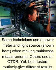
When a power meter and a light source are used to measure the loss in a fiber-optic link, they closely model what the final installed equipment will do. A signal is sent from one end (the source) to the other end (the receiver or power meter), and power lost in the link due to attenuation is measured. However, an OTDR works on a completely different principle.
There are 10 reasons OTDRs provide different answers from power meters when loss is measured on multimode fiber-optic links.
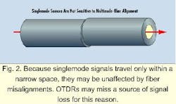
1. OTDRs measure length and loss via backscatter reflection. This technique is not a "through" measurement, but rather a reflection measurement. Conditions in the link that significantly affect backscatter may have a negligible effect on a multimode source. Such conditions include variations in core diameter and changes in attenuation when fibers of different characteristics are connected together.3. Because the OTDR sends the signal down the core of the fiber, mismatches in alignment at connectors that cause multimode losses are missed (see Fig. 2). Singlemode signals are essentially axial, so the higher-order modes are not present.
4. Because the light sent by the OTDR down the center of the fiber is not bouncing off the sides of the fiber as a multimode signal would, it takes a slightly shorter path. The singlemode signal thus has less loss than a multimode signal.
5. When OTDRs measure short lengths of fiber (as is typically seen in multimode-fiber applications), the receiver may saturate if a large reflection is seen. Until it recovers, the trace can't be use for a reliable measurement.
6. OTDRs require interpretation of the trace by a knowledgeable operator. Especially at a connection (where the pulse often has a curving slope), it is not clear exactly where to start or end loss readings. Ghost traces, programmed pulse width, dead zone, and other inherent factors can affect results.
7. The presence of a launch cable, if used in the OTDR measurement, will create another difference between a power-meter reading and an OTDR reading. When a power meter is used properly, the loss in a launch cable is zeroed out.
8. When the launch cable is subtracted from the measurement, OTDR users often go too far and also subtract or ignore the loss in the first connector in the link. By starting the measurement after the first connector, you immediately have up to 0.75 dB of "missing" loss in the link, since standards allow connections to have up to 0.75 dB of loss.
9. OTDRs reflect from the end of the fiber, which in most field-testing applications is the near end of the furthest connector. The OTDR does not measure the loss across the last connector, which could be another 0.75 dB of difference.
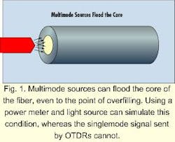
10. Power meters with multimode sources often have an overfilled launch condition. That is, the light from the source goes into the cladding as well as the core, just like a multimode transmitter would do (see Fig. 1). This tendency represents additional loss not seen with an OTDR measurement, because the test signal goes down the center of the fiber.
What about singlemode loss testing? There can still be a significant difference between power meters and OTDRs. These differences, partly described above, include backscatter versus through measurements, receiver saturation, trace interpretation, launch cables, and far-end connectors.
Look no further than the standards for clarification on this issue. In TIA 526-7 (also called OFSTP-7), "Measurement of Optical Power Loss of Installed Single-Mode Fiber Cable Plant," two methods for measuring loss are described. Method A uses a power meter and light source, while Method B uses an OTDR. This standard states in part: "Method B provides an indirect estimate of the loss of the cable plant...generally, more accurate or reliable values may be obtained by using Method A. If the values obtained by Method A and Method B differ from each other, the results of Method A shall be accepted as correct."
OTDRs are useful tools for locating fiber faults and characterizing the loss in installed fiber connections. When used correctly, they can pinpoint the causes for excess loss and verify that splices and connections are within appropriate tolerances. However, the most accurate, repeatable, and reliable method for measuring overall link loss is to use a power meter and light source. u
Mark Johnston is director of technology development at Microtest Inc. (Phoenix).


