Manufacturing, Packaging & Integration
Proper optical performance in fiber-optic devices requires adherence to mechanical tolerances in the micron range. As a result, microscopes play an important role in many inspection and assembly processes such as pigtail assembly, inspection of thin-film filters (TFFs), and laser alignment. Selecting the right microscope for the job can have a major impact on yield and productivity.
For example, Greenough-style microscopes, which actually consist of a separate compound microscope for each eye, are compact yet provide a relatively large viewing area and ample distance between the bottom of the microscope and the workpiece—two factors that are important in pigtail assembly. On the other hand, the common main objective (CMO) microscope, which is equipped with a single large objective lens, provides more flexibility by allowing attachment of accessories to the microscope. That makes it well suited for inspecting TFFs with polarized light, which helps to detect tiny defects. Also, when selecting a microscope, pay careful attention to ergonomics to maximize operator comfort and productivity.
While fiber optics has been around for a long time, large-scale production only began in the 1990s, when rapidly increasing bandwidth demand started to outpace the capacity of the installed base of copper wiring. The fiber optics manufacturing infrastructure has not changed much from the time when fiber-optic components were primarily produced in low volume for use in research and development applications.
In the past, nearly all manufacturing operations were performed manually, with processes largely unchanged from those used to build laboratory prototypes. With the sharply increasing demand at the beginning of the last decade, the components industry had to ramp up production so quickly that there was no time to automate. Instead, the existing processes were simply replicated.
Even though fiber optics manufacturers are now working on automating higher-volume processes, this goal cannot be accomplished overnight. One reason is the lack of equipment suppliers, mainly because the unique features of photonics manufacturing present substantial entry barriers for existing semiconductor suppliers. The current fiber optics manufacturing environment requires a wide range of diverse processes such as specialized wafer processing, fiber-handling, thin-film production, device packaging, subcomponent assembly and tuning, component splicing and packaging, testing, adjusting, and packaging for rigorous environmental specifications.
Most of these processes will continue to be performed manually for a considerable period of time, and it's difficult to see how some processes will ever be automated. As a result, many fiber optics manufacturers have recently focused considerable attention on providing their assembly and inspection personnel with tools that allow them to meet demanding tolerance requirements while increasing productivity.
Microscopes are an absolute requirement for many manufacturing processes, because the necessary high mechanical tolerances cannot be resolved by the naked eye. In most cases, stereomicroscopes are needed because of the three-dimensional (3-D) character of the work. Stereomicroscopes impart a spatial image of 3-D objects by allowing each eye to observe the object from a different direction. The brain processes the two images and fuses them into a single stereoscopic image.
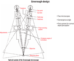
There are two basic stereomicroscope designs. The first was proposed by the American zoologist Horatio S. Greenough in 1892 and is still called the Greenough microscope. It consists of two separate compound microscopes—one for each eye—each arranged with a different convergence angle (see Figure 1). Both microscopes are focused on the same specimen and provide each eye with an enlarged image from the same viewing direction as if they were being observed with the naked eye.Greenough microscopes use convex lenses for both the objective lens and ocular lens, which would normally result in an image that appears upside down and backwards. Consequently, porro prisms are fitted between the eyepieces and objectives to reverse the image so it appears correctly to the human eye. A porro prism is a system in which two separate prisms are positioned in an offset relationship.
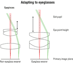
The angle between the two sets of lenses in a Greenough microscope should be selected to provide a comfortable and natural observation position. The necessity to position both sets of optics close to each other—to align them with the viewer's eyes—limits the working area where the sample can be positioned and the amount of magnification that can be provided.Provision must also be made for eyeglass wearers (see Figure 2). The distance between the eye point—defined as the position where rays from all points in the field of view come together and where the eye must be positioned to see them—and the last lens' surface must be increased from a typical 12-22 mm to provide a full field of view for eyeglass wearers. Because the field angle is the same for both types, the eyepiece lenses for eyeglass wearers are much larger.
In instruments based on the Greenough principle, the focal planes for the two optical channels are tilted with respect to each other and in correspondence to their convergence angles. There is a very limited area where the 3-D specimen appears sharply in both beam paths. Fortunately, the human brain is able to adapt quite easily to slightly unfocused images and automatically prefers the sharp images whether they are provided to the left or right eye.
That is more of a problem for two-dimensional objects, which can be addressed by tilting the specimen. A corresponding advantage to the tilting of the optical channels is that instruments based on the Greenough principle have a considerably greater depth of focus in the Z-axis direction. That presents a significant advantage when looking at an object that is contoured, such as an optical fiber.
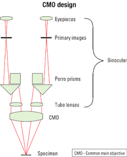
The other stereomicroscope design is called common main objective . This design uses two objects that produce a separate image for each eye, along with a CMO lens, which covers both beam paths and focuses them to the specimen (see Figure 3). The specimen is located in the front focal plane of the common main objective, so there are parallel beams between the CMO and the two objects, producing an image in infinity.The main advantage of the CMO principle is that the distance between the CMO and the tube lenses may vary somewhat without negatively affecting the image quality or position. That means it is easier to insert optical modules and accessories between the CMO and the tube lenses. The only exception to this rule is that "vignetting" may occur, a shadowing at the outside edge of the field of view caused by exceeding the focal length of the microscope. In many cases, there is a magnification changer just behind the CMO. Often an optical module with a beam splitter is inserted, for example, to allow a second observer to mirror in a second image.
However, CMO instruments are subject to several possible optical aberrations. One is the "dome effect," where a flat object is seen as having a domed surface. This effect is caused by the beam paths not passing through the center of the CMO lens, which makes the image axially asymmetrical.
Field curvature , another aberration that can occur with a CMO instrument, happens when a flat object is imaged by an optical system in such a way that the center and edges of the field cannot be brought into focus at the same time. Field curvature can be corrected by using a flat-field objective or appropriately designed secondary optics.
The beams of a CMO stereomicroscope travel eccentrically through the CMO, which result in the elimination of asymmetrical aberrations and an identical image being presented in both eyepieces. The corresponding weakness of a CMO stereomicroscope is that more and larger lenses are required to produce an image using this approach. The result is that a CMO stereomicroscope costs considerably more than one based on the Greenough principle. In addition, the extra lenses required with this approach reduce the working area of the device.
Depending on the need, Greenough stereomicroscopes provide a low-cost, compact instrument with a large working distance and excellent image quality in the center of the depth of field. The simplicity of the Greenough approach avoids several aberrations that can occur with CMO instruments.
On the other hand, CMO instruments are modular and can be easily upgraded at any time. There is a wide range of binocular tubes available as well as optional accessories to adapt the instrument to the application. It's easy to change an objective lens, add a camera phototube, or add a mercury bulb for fluorescent imaging.
Another advantage of the CMO instrument is that the image is equally sharp in both channels. The instrument is also better suited for use with a camera for documentation purposes, because the camera will capture the same view regardless of which channel is used to collect the data.
One important application for stereomicroscopes is pigtail assembly. A typical pigtail consists of a glass ferrule that is a few millimeters in diameter into which a 125-micron bare fiber strand is inserted. Pigtails are used as the primary means for attaching two fibers together or attaching a fiber to an associated device such as a filter or laser.
The small size of pigtails and the need to carefully align them while they are attached to each other using adhesives make some type of magnification a must in nearly every case. Most fiber optics manufacturers use a Greenough stereomicroscope mounted on a boom stand to perform this operation. The key advantages of the Greenough design in this application are its long working distance, which provides plenty of room for fixtures and tools, and its low cost, which is important since this operation is found throughout most fiber optics assembly plants.
Thin-film filters are other very common fiber-optic components that usually require the use of stereomicroscopy. TFFs are made in a vacuum coating chamber by depositing thin alternating layers of two dielectric materials on a polished glass substrate. TFF glass windows typically contain over 100 layers of alternating index material.
After they are produced, these filters need to be carefully inspected to ensure the absence of tiny holes that will damage the performance of these devices. Even with high levels of magnification, these holes are difficult to detect in ordinary light, because there is so little contrast between the holes and the base material. A CMO microscope is the preferred choice for this application, because it can easily be fitted with a polarizing attachment and provides the very high image quality required by this application.
Another critical manufacturing operation is the inspection of laser diodes and waveguides to ensure they are not experiencing leakage of light. A closely related task is the alignment of components such pigtails, filters, and lenses in precise proximity to each other before an active alignment process in which the device is powered up and components are moved into final position based on the readings of a light meter. These operations are difficult due to the devices' small size. Also, the light is typically in the infrared range, which is not passed through the optics of conventional microscopes. These issues can be addressed by modifying the microscope with special lenses that do pass through infrared frequencies.
In addition to selecting a microscope that provides the operator with the visual information needed to perform assembly or inspection operations, reducing stress on the operator should be a concern. Optical aids, when used for many consecutive hours, can place enormous demand on the eyes, the musculo-skeletal system, and the observer's power of concentration.
If the viewing height is too low, the observer will be forced to bend forward while working, with resultant muscular tension in the neck region. In the ideal microscope, the viewing height and viewing angle should be adjustable to the physical build of the user. Also, a variable viewing height is the best way to prevent sedentary posture. It permits observers to adopt a personal sitting style and change their posture with the natural human urge to move from time to time.
Two conditions must be met for frequently used controls such as the zoom and focus knobs to achieve good ergonomics and user comfort. First, these controls must be as low as possible on the microscope; second, it must be possible to operate the controls with the forearms supported and the shoulders relaxed. To avoid unnecessary stress to the shoulder girdle, the need to stretch the arms out too far should be avoided. Ergonomically, that means the best posture is with the arms horizontal or sloping slightly downwards and with the hands resting on their edges. The drive knobs should neither be too slack nor too tight. Ideally, their ease of movement should be adjustable to meet individual requirements. For higher magnifications, there should be a fine-focus mechanism.
Ergonomics at the workplace naturally relate not only to the instrument itself, but also to the chair and table that are used. The limited adjustment possibilities of the instrument itself can accommodate finer ergonomic tuning, but first the chair and table must be chosen and arranged to meet more basic ergonomic requirements. Their height and tilt must ensure that the whole person, from head to foot, can sit and work in the best possible posture.
Because microscopic observation generally extends over a considerable period of time and requires great concentration, posture is important. Generally, the ideal in terms of relaxed and comfortable sitting is offered by a microscopy table with adjustable height and a sufficiently large surface on which to rest the hands, combined with a chair that is adaptable to the physical build of the user, which has a tall backrest tiltable backward up to 30 degrees. If the task requires the user to lean forward, this forward tilt should not exceed 20 degrees.
All in all, stereomicroscopes play an important role in fiber optics manufacturing. Selecting an instrument with the right optical and ergonomic properties for critical assembly and inspection operations will maximize both yield and productivity.
Doug Giszczynski is a senior product manager for stereomicroscopy at Leica Microsystems Inc. (Bannockburn, IL).


