Best Practices for Validating 400G+ Transceivers
Communications service providers (CSPs) and network equipment manufacturers (NEMs) are racing to keep up with increasingly complex technology and explosive growth in data communications. At the core of high-speed networks are pluggable transceivers operating at rates ranging from 1G to 400G, each using complex and constantly evolving technology.
These new-generation transceivers are mass produced, at a pace of thousands per day, and they must meet strict quality and reliability standards to function accurately in today’s demanding high-speed networks, including 5G. To maintain that speed of production, manufacturers need simplified instruments capable of providing quick and accurate transceiver evaluation and validation.
In this article, we’ll take a look at testing the latest generation of 400G transceivers and cover topics including:
- Overview of PAM4 modulation and optical transceivers
- Challenges that manufacturers face while validating transceiver units at different stages of manufacturing
- Description of the electro-optical full validation of transceivers, including both parametric tests (during manufacturing) and functional tests (post manufacturing)
- Best practices and efficient tools available for testing and qualification of pluggable transceivers.
The emergence of PAM4
Globally, numbers of both electronic devices and connections are growing faster than human populations, with users connected to, on average, more than one device. We are also experiencing a dramatic rise in bandwidth requirements, a demand driven by hyperscalers such as Facebook, Netflix, and Amazon. This trend is fueling an increase in the production and sales of optical transceivers.
In LightCounting’s Optical Communications Market Forecast published in October 2019, the CAGR of global optics transceivers sales hit 14% between 2003-2016 with the same rate of growth predicted for the years 2020-2024 (see Figure 1). The IHS Markit Telecom Optics & Components study published in May 2018 segmented this growth by transmission capacity. The report shows that 200G appears in 2017, then as of 2019 the combined mix of 200G and 400G ramps up to become the most deployed rate. In summary, there is a high demand to produce and test thousands of 200G and 400G transceivers per day, and most of the units are four-level pulse amplitude modulation (PAM4) based.
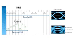
As discussed, PAM4 doubles the density of data with respect to NRZ modulation. PAM4 technology enables lower bandwidth components and materials and the reduction of conveyed wavelengths. Consequently, PAM4 leads to a reduction in the number of deployed fibers. At the end of the day, transmission costs are also reduced.
PAM4-based components deliver advantages but also introduce big challenges for testing, since analyzing the volume of a four-level system is more complex than NRZ. PAM4’s amplitude is three times shorter than that of NRZ. PAM4 has lower signal-to-noise ratio and tighter spacing between encoding levels; consequently, it is more susceptible to noise. Another drawback is the consumption of higher power by PAM4 transceivers.
Overview of today’s optical transceivers
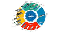
Today’s high-speed transceivers come in a variety of form factors (see Figure 3). The first form factor is SFP, ranging from SFP+ for 10G to SFP56-DD for 100G. The second form factor is CFP, supporting 100G interfaces with CFP4 and moving up to CFP8 for support of the first generation of 400G transceivers. The third form factor is QSFP. QSFP transceivers range from QSFP+ for 40G to QSFP-DD for 400G. Finally, last but not least is the OSFP form factor. Also enabling 400G rates, OSFP has a huge potential with support for 800G rates.
Testing transceiver performance
Testing electrical and optical parameters is an essential step in the manufacturing process to guarantee compliance to specifications and industry standards. Transceiver vendors are always looking for simplified approach capable of providing an accurate and quick evaluation. A full evaluation involves electrical and optical tests. Tests are divided into categories. The first one is the parametric test, which is performed during the design and production of the transceiver. The second category is the functional test; done mostly for quality control, it is performed once the transceiver is fabricated.
Parametric tests
Parametric tests are focused on the performance of internal components packaged inside the transceiver, mainly the transmitter optical subassembly (TOSA) and the receiver optical subassembly (ROSA). Once a client’s line arrives at the TOSA, the signal is converted from electrical to optical. Then, the TOSA sends and transmits the information. On the opposite direction (line side), the optical signal arrives at the ROSA, which is essentially a photodiode. The ROSA converts the signal from optical to electrical and, finally, this signal is once again injected into the client's line.
In addition, optical tests—average optical power, wavelength verification, side-mode suppression ratio, and channel flatness—are performed.
Optical power
TX and RX optical power are very important to ensure the normal communication of the transceivers and are measured using an optical power meter. Only when the transmitter and the receiver optical power are within desired thresholds is the transmission distance ensured.
Wavelength verification
Wavelength verification measures the central wavelength of the laser emission and is performed by either a wavemeter or an optical spectrum analyzer (OSA). The required wavelength accuracy is ±20 pm. When verifying wavelengths in transceivers, tests are run at different temperatures to test how the transceiver behaves under the target temperature range. This is important as optical components are very sensitive to temperature variations.
Side-mode suppression ratio
Side-mode suppression ratio (SMSR) testing is performed with an OSA. The SMSR is the power difference between the main peak power and the first side modes on the left and the right. The minimal value for SMSR is 30 dBm. This test, like wavelength verification, should be performed at different temperatures.
Channel flatness
Channel flatness is the difference in power between two continuous lengths and this test is also performed using an OSA. The maximum compliant value is +4 dBm.
Functional tests
Once the manufacturing process is complete, functional tests are performed on the transceiver. Functional tests verify bit error rate (BER), optical modulation amplitude (OMA), extinction ratio (ER), transmitter and dispersion eye closure (TDECQ) and receiver sensitivity.
Bit error rate
BER tests verify generated and detected rates. BER is the parameter that best describes the overall health of a communication system. It is the major indicator of network performance, and a healthy value is around 10-12. A good BER value is achieved when there is a significant difference between the logical 0 and the logical 1 level in the eye diagram. Speaking of the eye diagram, the next functional tests are related to this parameter.
Optical modulation amplitude
OMA defines the maximum and minimum optical amplitude at the transmitter. To perform this test, the line side of the transceiver is connected to the optical oscilloscope.
Extinction ratio
ER uses a ratio of the power used to transmit logical level 1 to the energy used to transmit a logic level 0. ER of PAM4 signals is the ratio between the average power of signal three level and signal coming from zero level. The extension ratio is determined by performing a statistic analysis from the eye diagram.
Transmitter and dispersion eye closure
TDECQ measures if the performance of a transmitter meets the basic requirements for transmitting PAM4 signals. It is computed and deduced from the eye diagram using an optical oscilloscope. TDECQ is a key predictor of assisted performance for a PAM4 component.
Receiver sensitivity
Receiver sensitivity is a traditional test performed to characterize receiver performance. It is defined as the minimal received optical signal power at the Rx to achieve certain bit error rate value in a back-to-back configuration. These parameters show the quality of the receiver design. In a nutshell, the better receiver sensitivity, the better assisted performance in terms of longer transmission distances.
End-to-end transceiver qualification set-up
End-to-end transceiver qualification setup uses a BER tester connected to the module compliance board (MCB), then to the transceiver for the electrical line. The optical signals then move through a switch to split the optical signal for all the parametric tests, to the VOA and the power meter for the sensitivity receiver test, and to the optical spectrum analyzer for the ER, wavelength verification, and TDECQ, respectively.
Using an oscilloscope enables the enhancement of an optical signal. For example, in the Tx eye, there are signal processing methods available – pre-emphasis and equalization. Pre-emphasis enables the manipulation of electrical levels to enhance eye amplitude. In addition, at the Rx eye, equalization is useful to compensate the attenuation caused by the losses coming from the line, either fiber or copper. Also, it is strongly recommended when evaluating all these tests that permanent temperature monitoring occur during the BER test.
Conclusion
In summary, 400G technologies are currently being rolled out thanks to advances in optical communications. To meet the growing demands of traffic, transceiver vendors have adopted PAM4 to implement eight lanes of 50G or four lanes of 100G for different variants of OSFP and QSFP-DD, as an alternative to classical non-return-to-zero (NRZ)-based interfaces. The novel optical transceiver architectures support the transmission up to 400-Gbps Ethernet data over either multiwavelength or parallel fibers. However, the multilevel modulation involves a higher complexity for analysis, equalization, and validation.
As a result, it is more complex to validate 400G interfaces because users must consider several aspects of the device under test that can drastically affect performance (e.g., power consumption, temperature, etc.).
Aldo Gutierrez, PhD. is a product specialist in manufacturing design and research at EXFO. At EXFO, Aldo supports and launches tactical activities related to optical spectrum analyzers, tunable filters, BER testers, optical scopes, and 400G transport and datacom solutions.
About the Author
Aldo Gutierrez
Product Specialist
Aldo Gutierrez, PhD. is a product specialist in manufacturing design and research at EXFO. At EXFO, Aldo supports and launches tactical activities related to optical spectrum analyzers, tunable filters, BER testers, optical scopes, and 400G transport and datacom solutions.


