Not All FTTH Architectures Are Created Equal. Which One is Right for You?
FTTH Architecture Overview
Not all FTTH networks are built the same. Since construction and outside plant account for the majority of total network costs, getting the architecture right has a major impact on the business case. The network architecture can also impact time-to-market, labor/training requirements, future upgradeability, network performance, and ultimately customer satisfaction.
This paper provides an overview of two fundamental FTTH architecture categories – centralized and cascaded – that determines where in the network the fiber is split. Splitter placement and split ratios strongly impact the location and amount of fiber required, and hence the cost of deployment. This is followed by a discussion of several designs. The choice of fiber all the way to the home, or of using copper in the final drop to the customer premises (FTTdp) is also examined. This work draws upon over a decade of experience that CommScope has in helping service providers around the world design, build, and maintain FTTH networks, including variations such as FTTN, FTTC, and FTTB networks.
This overview paper is the first in CommScope’s FTTH Architecture Series. Papers in this series discuss different architectures, along with their benefits, trade-offs and disadvantages, providing an objective look at each architecture to help service providers make informed decisions.
Centralized or Cascaded?
Or, how many splitter stages?
The Passive Optical Network (PON) is the optical fiber infrastructure of an FTTH network. The first crucial architectural decision for the PON network is that of optical splitter placement. The centralized approach uses single-stage splitters located in a central hub in a star topology. The cascaded approach uses multi-stage splitters in a tree-and-branch topology.
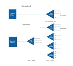
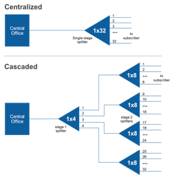
A centralized approach typically uses a 1x32 splitter located in a fiber distribution hub (FDH). The hub may be located anywhere in the network. The splitter is directly connected via a single fiber to a GPON optical line terminal (OLT) in the central office. On the other side of the splitter, 32 fibers are routed through distribution panels, splice ports and/or access point connectors to 32 customers’ homes, where it is connected to an optical network terminal (ONT). Thus, the PON network connects one OLT port to 32 ONTs.
Figure 1: Comparison of Centralized and Cascaded architectures.
A cascaded approach may use a 1x4 splitter residing in an outside plant enclosure. This is directly connected to an OLT port in the central office. Each of the four fibers leaving this stage 1 splitter is routed to an access terminal that houses a 1x8, stage 2 splitter. In this scenario, there would be a total of 32 fibers (4x8) reaching 32 homes. It is possible to have more than two splitting stages in a cascaded system, and the overall split ratio may vary (1x16 = 4 x 4, 1x32 = 4 x 8, 1x64 = 4 x 4 x 4).
A centralized architecture typically offers greater flexibility, lower operational costs and easier access for technicians. A cascaded approach may yield a faster return-on-investment with lower first-in and fiber costs. When deciding on the best approach, it’s important to understand these architectures in detail and weigh the trade-offs.
Centralized using Fiber Distribution Hubs (FDH)
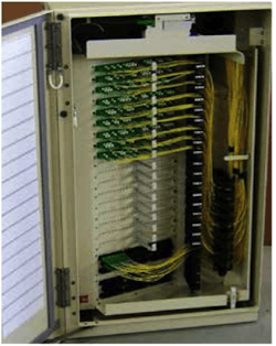
This architecture centers on the FDH where every end user or building in the neighborhood is represented. It makes very efficient use of the splitters, maximizes accessibility, provides easier troubleshooting and accelerates turn-ups/ reconfigurations.
Figure 2: A Fiber Distribution Hub
The architecture typically begins with a 1x32 splitter placed inside the FDH, with the 32 split fibers routed through distribution panels, splice ports, and/or access point connectors to the ONTs at 32 homes. A series of terminals make up the distribution side of the FDH. These terminals may be integrated into the network using splices, connectors or a combination.
While spliced terminals offer great flexibility in how a network can be installed and the lowest optical loss, they require much higher labor costs and additional time for deployment. Almost every network will employ some combination of splices and connectors, where they make the most sense.
For connectorized options, hardened connectors add some significant benefits. These are specifically designed for use harsh environmental conditions and will speed up deployments while reducing labor/installation costs. The FDH can be connectorized with hardened multi-fiber optical connectors (HMFOCs) for easily connecting 12-fiber OSP cables in the distribution network. Both the FDH and terminal tails can be connectorized to just plug together, providing a more fully connectorized architecture.
A fully connectorized, centralized approach using an FDH offers some attractive benefits: speed of deployment; maximum long-term flexibility; and future-proofing aspects. Maximizing the use of connectors instead of splices whenever it makes sense also enhances the accessibility of the network. One ideal area for a centralized approach is where take rates are not guaranteed, but may increase steadily as the area is further developed over time.
Centralized using Closures
In this architecture, the feeder cable from the central office is connected to a closure at the fiber distribution point of the network. The closure performs as the splitter housing. However, while an FDH leverages connectorization as much as possible, the closure system is typically spliced together. Still, the closure remains accessible for adding splitters at a later time, so it’s possible to deploy the network for an expected take rate and add splitters if the take rate increases.
Additional closures can be deployed downstream from the main closure to further extend the network.
Figure 3: Drops at stage 2 splitter
The architecture begins with the feeder cable running from the central office to the closure, where it is spliced to the splitters inside. The splitter outputs then extend out to a few splice closures. This architecture is designed for very small distribution areas, so there are typically only a few splice closures and a relatively small splitter count. The distribution fibers are spliced into drop cable splice closures, such as the hybrid connector-splice closures, and drop cables are spliced in for connecting the ONTs at each home.
This architecture is typically based on splicing, so equipment costs are minimized. But lower initial costs may be offset as time goes on by reduced flexibility and higher maintenance costs. Still, the architecture is ideally suited for very small distribution areas, such as one requiring only two closures off the main closure.
Cascaded using Closure
From the central office, the feeder fiber enters the closure and passes through the first splitter (see Figure 1, stage 1 splitter). The output fibers then feed into smaller closures, or fiber access terminals, that are closer to the customer. At each smaller closure, a distribution fiber enters another splitter. The drop cables from each customer premise are then connected to the outputs of these splitters to complete the network connections.
The cascaded with closures architecture is typically spliced from the hub closure to the splitter inputs at the fiber access terminals.
The feeder fibers are spliced to the splitter inputs and the distribution fibers are spliced to the splitter outputs. In the fiber access terminals, the distribution fibers are spliced into the splitter inputs. There are pre-connected adapters on the splitter outputs to allow fast connections with pre-connectorized drop cables. This “half-spliced, half-connectorized” installation accounts for the majority of today’s cascaded networks. Connectorization at the customer side enables faster changes and more flexibility.
In areas where high take rates are projected, or in rural areas where fiber costs become more significant, this approach can be a great fit.
Cascaded with Fiber Reuse
This architecture is extremely fiber-efficient. To illustrate this architecture, let’s take a 1x32 split ratio and a single 12-fiber cable placed throughout the service area. This single cable is used as both the feeder fibers and the distribution fibers. Fibers 1 to 8 are the feeder fibers, and each will connect from the central office to a stage 1 splitter within the service area. Fibers 9 to 12 are the distribution fibers that connect a stage 1 splitter to a stage 2 splitter. These distribution fibers are divided into segments along the length of the cable, with each segment serving only the local area. Since the distribution fibers 9 to 12 do not directly connect back to the central office, they are “reused” throughout in each local area.
Figure 4 illustrates the fiber reuse architecture. Fibers 9 to 12 in the cable are reused eight times, because there are eight segments – one segment for each feeder fiber 1 through 8. Each feeder cable will have a 1x4 split in the first stage and 1x8 split in the second stage. This then connects directly to the home via drop cables, resulting in 32 homes served. Thus a single 12-fiber cable can service up to 256 homes by combining feeder and distribution functions.
The fiber reuse model is particularly effective in a large rural or MDU setting because all the components, including the fiber itself, are relatively small. The terminals or closures are also quite small, having minimal aesthetic impact to the neighborhood or building.
It should be noted that the fiber reuse architecture can be significantly more difficult to design, engineer, document and service. However, it is extremely efficient in terms of fiber usage, and equipment costs are lower. This architecture should seriously be considered in large rural areas or for MDU applications where smaller equipment size, ease-of-installation and overall aesthetics are important requirements.
Figure 4: Fiber reuse architecture for 12-fiber cable.
Cascaded with Fiber Indexing
Fiber indexing uses a fully-connectorized system and allows installers to use a cookie-cutter approach to build out the network. The exact same components are “daisy-chained” together, limiting the need for custom cable assemblies or splicing. The basic building block, which is repeated throughout the service area, includes a connectorized terminal, with a connectorized tail and connectorized single- and multi-fiber outputs.
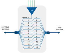
The indexing begins with a 12-fiber cable entering the first terminal. In the terminal, fiber 1 is routed to a splitter for servicing local customers and the remaining fibers are “indexed” or moved up as they exit the terminal to connect to the next terminal. Indexing means that the second fiber entering the terminal will exit as the first fiber to enter the next terminal, and so on in a daisy-chained fashion.
The terminal tails use Rapid Fiber cable spool technology to eliminate the need to store excess fiber. This technology allows any amount of fiber cable to be pulled from the spool back to the previous terminal without the need to cut specific lengths or store the excess cable. All the remaining cable is simply left on the spool, allowing fast and easy daisy-chaining of the indexing terminals.
Whereas traditional cascaded architectures require different terminals with different fiber lengths that require complex planning, fiber indexing uses a single configuration throughout the network.
There are several variations of this architecture, so it meets the requirements of many deployment scenarios. By using the same components over and over throughout the network, along with less overall fiber, the network can be installed faster and with lower overall installation costs.
Fiber indexing offers several attractive benefits to service providers choosing a distributed architecture for their access network. Using the same terminal, same splitters, same fiber cable and adding cable spooling technology makes a good case for fiber indexing in many access applications. The addition of connectorization whenever it makes sense reduces the need for more highly-skilled labor, further decreasing overall costs.
Figure 5: Fiber Indexing architecture (daisy-chained).
Figure 6: Fiber Indexing terminals all have the same configuration, which speeds up installation.
The promise of FTTdp: Gigabit speeds over the existing copper plant
The approximately 200 meters (600 feet) from the drop to the customers’ premises is typically the most cost and labor intensive part of any deployment. Fiber To The Distribution Point (FTTdp) is an architecture that takes fiber to the distribution point, then uses the existing copper local loop to bridge the final distance to the home. It avoids or defers the relatively expensive civil works of laying fiber all the way to the home.
Several copper technologies can be deployed with FTTdp: G.fast, VDSL2, or G.hn. G.fast promises peak data rates approaching 1 Gbps at short distances. VDSL2, which can be further augmented by bonding and vectoring, can achieve a theoretical 200 Mbps over a longer distance. G.hn is an evolving technology designed to work over copper local loop, power lines, and coaxial cable with data rates in the sub-gigabit range.
For incumbent service providers, FTTdp can be considered the next and possibly final step in getting fiber closer to the subscriber, short of going all the way as with FTTH. The initial step was FTTN (where the Node is a remote DSLAM), then followed by FTTC/FTTB (Curb or Building). Extending fiber deeper into the access network is driven by the exponential growth in demand for bandwidth – which shows no signs of abating in the near-, mid-, or long-term.
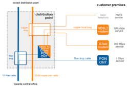
In the FTTdp architecture, a PON ONT is located at the distribution point where the copper subscriber loops are patched or spliced – instead of in the subscriber’s home. From the network side the fiber drop terminates at the ONT; from the subscriber side the copper wiring from multiple homes also terminate at the ONT. The CPE equipment in the home is a VDSL2/ G.fast modem. Besides transmitting data, the modem may also supply power to the ONT in a “reverse powering” arrangement, since the ONT will often be located outdoors with very limited access to power.
The distribution point is an ideal intercept point for copper to handoff to the fiber network (see figure 7). Its precise location would be determined by existing and planned cable conduits and pathways – which could mean aerial, in a building basement, mounted on a pole, in an outdoor cabinet or pedestal, or buried underground in a small hand-hole. The wide range of locations necessitates a compact design with a small form factor, and hardened for operation in harsh environments. Heat dissipation of the VDSL2/G.fast/ PON ONT (which increases with the number of subscribers served) may be an issue, particularly in space-constrained locations such as underground hand-holes.
The implication for network architecture is that less fiber is required for FTTdp compared to FTTH, since the PON ONT (which requires a single fiber) now aggregates multiple (typically 4-8) subscribers. FTTdp can work equally well with centralized or cascaded splitting architectures. However with multiple subscribers sharing a fiber drop, fiber split ratios in the distribution network could be lower.
A key provision for FTTdp will be maintaining flexibility for future upgrades. Factors such as deterioration of the copper local loop, subscriber take-up rates, and the competitive threat of other service providers installing fiber will likely necessitate a combination of FTTdp for the broader market and FTTH for select customers – likely at the level of the distribution point. Upgrading a subscriber from FTTdp to FTTH must be a fast, simple, and reliable process. Hence considerations for spare fiber capacity and fiber split ratios that can be adjusted according to demand should be taken into account.
Throughout 2015, FTTdp is expected to rapidly mature from the proof-of-concept stage into a robust and industrialized technology. CommScope’s engineering and product development programs are contributing to this progress to help make FTTdp a viable solution for service providers.
Figure 7: FTTdp architecture at the distribution point.
Conclusion
This paper reviews a number of centralized and cascaded FTTH architectures. As the expectation and business plan for every deployment is unique, there is no “one-size-fits-all” architecture solution. Knowing the advantages and disadvantages of each will help in the selection process.
CommScope has comprehensive and in-depth experience in designing, implementing, and maintaining fiber and FTTH networks around the world. The FTTH Architecture Series is a complete set of white papers that explore the key issues and decision criteria for building best-in-class FTTH networks. For more information, please visit www.commscope.com
