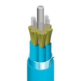
Fiber optic cables have evolved over the years as the demand for bandwidth to support communication needs has increased exponentially. In particular, the fiber density—the ratio of the number of optical fibers to the cable outer area—has continued to increase. Today, ultra-high density, micro-cables are commonly used in applications where space is limited. This can include micro-cables that are blown into ducts or routed through data centers. In each case, cables are designed to be compact, yet provide the robustness required to protect the optical fibers.
The primary purpose of a fiber optic cable is to protect the optical fiber contained within. During installation and throughout the life of a cable, it may be exposed to a variety of mechanical forces and environmental conditions. As such, stakeholders have worked together to develop several documents that identify typical conditions to which cables may be exposed, depending on the application, and define performance expectations under such conditions. For example, Telcordia Technologies has published GR-20-Core, Generic Requirements for Optical Fiber and Optical Fiber Cable, and the Insulated Cable Engineer Association has published ANSI/ICEA S-87-640, Standard for Optical Fiber Outside Plant Communications Cables.
While traditional aerial and direct buried applications require a robust cable that is capable of withstanding severe forces as described in the aforementioned industry documents, these cables are often over-designed for many applications. Particularly in FTTx environments, where higher fiber density and reduced cable diameter is preferred, many applications allow for alternate designs that may not be as rugged as traditional cables. Such cables are often referred to as micro-cables. This article will focus on micro-cables that are designed for three different applications: outside plant (OSP) cables for use in micro-ducts, indoor cables for use outside of ducts, and indoor cables for use within micro-ducts.
OSP Cable
Traditional OSP Cable
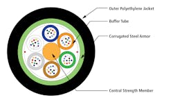
OSP cables typically consist of loose groups of fibers within buffer tubes, where multiple tubes are SZ stranded together over a central strength member (CSM). The stranded core may be covered with additional strength members and/or corrugated armor along with the outer jacket(s). Figure 1 shows the construction of a typical OSP cable, suitable for direct burial.
Figure 1—Traditional OSP Cable
Traditional OSP cables are often designed and tested to meet the requirements of GR-20-Core. In particular, this standard defines test methods and criteria to determine impact and compression resistance, tensile strength, and operating temperature ranges for cables. The buffer tube material and dimensions can have a significant impact on each of these characteristics.
Optical fibers use light waves to transmit signals. As the light wave travels down the fiber, some of the power is naturally lost as light escapes from the core. In addition, macro-bends and micro-bends of the fiber can cause additional attenuation losses. For example, as the buffer tube contracts at the cold operating temperature, the fiber may buckle if there is not enough free space within the buffer tube, creating significant macro-bending loss. Alternatively, if fibers are pulled taut against a rough buffer tube surface under the tensile loads and bends applied during and after installation, fibers may experience significant micro-bending loss.
In order to overcome these issues, buffer tubes have traditionally utilized a large inner diameter (ID) to provide considerable free space for the fibers, resulting in a large outer diameter (OD). The large OD allows for a large CSM, which contributes significantly to the tensile strength of the cable and limits contraction at cold temperatures. However, this design results in a large cable OD, and therefore, low fiber density. Fiber density is defined as the ratio of the number of fibers to the cross-sectional area of the cable. For the 72 fiber, traditional OSP cable shown in Figure 1, the fiber density is 46 cm-2.
OSP Micro-Duct Cable
Fiber optic ducts, typically plastic tubes, have been used since 1981 as a conduit to route cables and limit their exposure to many external forces.1 Initially, the ducts used traditional OSP cables, but they were often over-designed for these applications. Naturally, cable manufacturers quickly began developing smaller, less robust cables to take advantage of this technology. As cable sizes continued to decrease, duct manufacturers were able to develop smaller ducts. In the 1990s, this led to the development of multi-tube ducts. Where a traditional, 1¼” duct, was suitable for one 288 fiber cable, the 1¼” multi-duct, containing five micro-ducts, was suitable for five 72 fiber micro-cables. This increased the fiber density of the duct system by 25 percent and started a trend that has continued into the 2010s.
Micro-duct cables were included in the third issue of GR-20-Core, which was released in 2008, although no requirements were defined. The fourth issue, released in 2013, refers to the requirements of IEC 60794-5-10 and allows for testing at lower levels than traditional OSP cable (since cables are installed within protective ducts). This is important to understand since, for a given fiber count, the size of the individual components—buffer tube, CSM and outer jacket—must decrease for fiber density to increase.
A reduction in the buffer tube size may result in a less compression resistant tube and less free space for the fibers within the tube, making the cable less resistant to compressive loads. Although data indicates that the buffer tube with higher fiber density is less compression resistant than the traditional tube, cable tests of recently developed micro-duct cables meet the standard requirements (standard loads) for compression resistance and impact resistance. This can be attributed to the construction of new micro-cables and the improved quality of today's optical fibers, as well as some overdesign in the traditional OSP cable designs.
Additionally, the reduced tube size and free space within the tube reduces the fiber strain free window, or the amount of strain applied to the cable before the fibers begin to experience strain. In loose tube cables where the buffer tube is stranded over a CSM, the fibers will actually pull to the inside wall of the tube, since this is the shortest path, prior to experiencing strain. Assuming the buffer tube has no excess fiber length (EFL), the strain free window, ∆H, can be estimated by calculating the relative change due to the difference in the helix along the centerline of the tube and the helix when the fibers pull to the inside wall of the tube.
Further, a reduction in size of the CSM, a significant contributor to the overall strength of the cable, results in higher cable strain than traditional OSP cables under the same tensile load. When combined with the reduced strain free window, OSP micro-duct cables are rated at lower tensile loads to limit the strain on the fibers. However, since these cables are jetted or blown into the micro-ducts, reduced tensile ratings are acceptable and significant increases in fiber density are achievable.
Table 1—Fiber Density Comparison for OSP Cables
Fiber Count | Fiber Density (cm-2) | |
Traditional OSP Cable* | Micr0-Duct Cable | |
72 | 69 | 159 |
144 | 63 | 294 |
288 | 91 | 224 |
432 | 114 | 346 |
*Non-Armored Single Jacket Cable
Future Development of Micro-Duct Cables
Recent development of 200 µm optical fibers will allow additional increases in fiber density, both with traditional OSP cables and micro-duct cables.
Indoor Cables
Traditional Tight Buffered Cables
In transitioning from OSP cables to indoor cables, the requirements change significantly, so the constructions of these cables change as well. Notably, indoor cables must be flame retardant, so that in the event of a fire, the cables will not propagate the flame and smoke throughout the structure. Further, cables must be more flexible to facilitate installation and fibers should allow for connectorization.
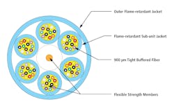
To support these alternate requirements, traditional indoor cables utilize 900 µm tight buffered fibers, semi-rigid or non-rigid strength members, and flame-retardant buffer and jacket materials. Figure 2 shows the construction of a typical indoor backbone cable with a fiber density of 25 cm-2.
Figure 2—Traditional Indoor Cable
Traditional Indoor Cables are often designed and tested to meet the requirements of Telcordia's GR-409-Core. Again, this standard defines test methods and criteria to determine impact and compression resistance, tensile strength, and operating temperature ranges for cables. Similar to OSP cables, materials and dimensions of indoor cables can have a significant impact on each of these characteristics. While this standard does distinguish between light duty interconnect cables and heavy duty backbone cables, it does not include requirements for indoor duct cables.
Indoor Micro-Cables
Since optical fibers are capable of carrying so much bandwidth, low fiber count cables are suitable for most single family residences. However, some applications, such as data centers, require high fiber count cables and benefit greatly from high fiber density, as they require less space and are less restrictive to air flow.
Because these cables may be installed directly outside of ducts, they are designed to meet the requirements for backbone cables. In this sense, cables meet the same mechanical, environmental and safety requirements as traditional, tight buffered indoor cables. However, because of the application and connector options, as early as 2002, early micro-cables were developed where bare fibers replaced tight buffered fibers.
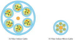
As seen in Figure 3, the change from tight buffered fiber to bare fiber provides an avenue to reduce the cable diameter and increase fiber density. However, additional changes are required. For one, the multimode fibers used in many indoor cables are more sensitive to macro-bending and micro-bending than single-mode fibers used in most OSP cables. In traditional indoor designs, the tight buffer over the fiber minimizes the fiber's exposure to these conditions. To limit these effects without the tight buffer, the choice of flame-retardant jacket material becomes critical.
Figure 3—Scaled Indoor Cable Comparison
Traditional flame-retardant jacket materials used for indoor cables include fluoropolymers and polyvinyl chloride (PVC). There are advantages to each, but engineered PVC compounds are preferred because of their cost and customizable physical properties.
In addition to mechanical protection, the flame retardant jacket materials limit flame spread and smoke generation when cables are exposed to fire. Commonly in data centers, cables are installed in plenum locations, and cables must be rated for use in these locations. Throughout the late 2000s and into the 2010s, cable manufacturers and PVC compounders have collaborated to develop higher performing flame retardant materials, allowing for continued increase in fiber density and fiber count per cable.
As shown in Table 2, with the proper materials and design,indoor micro-cables can meet the same mechanical, environmental and safety performance levels as traditional indoor cables with significantly reduced cable OD and increased fiber density. Further, micro-cables allow for higher fiber counts, including the GR-409-Core horizontal backbone compliant 288 fiber cable developed earlier this year.
Table 2—Fiber Density Comparison for Indoor Cables
Fiber Count | Fiber Density (cm-2) | |
Traditional Indoor Cable* | Indoor Micr0-Cable | |
72 | 25 | 136 |
96 | 23 | 111 |
144 | 28 | 130 |
288 | — | 108 |
Indoor Micro-Duct Cables
For many of the same reasons that micro-duct cables are beneficial in OSP environments, they are also beneficial in indoor environments. Similar to OSP micro-duct cables, indoor micro-duct cables are jetted or blown into ducts with compressed air. However, in this case, the micro-ducts are tubes made of flame retardant plastics, and can be independently safety listed, enabling future system expansions.
Once again the micro-duct prevents these cables from exposure to many mechanical forces. However, the most recent revision of GR-409-Core, released in 2008, does not address indoor micro-duct cables. While the previously discussed indoor micro-cables can be used within ducts, development of ultra-high fiber density indoor micro-duct cables, also called air blown fiber, began in 2009. These cables are designed and tested to meet the requirements of interconnect cables.
Material selection is again critical as these cables must meet the same safety requirements as other indoor cables, while providing the proper stiffness for proper installation. Replacing buffered subunits with bundled fibers allows for ultra-high fiber density. Figure 4 compares a 72 fiber indoor micro-duct cable with a fiber density of 453 cm-2 to the previously discussed Indoor micro-Cable.
Figure 4—Scaled Indoor Micro-Cable Comparison
Future Development of Indoor Micro-Cables
In addition to development with 200 µm fibers, work is ongoing with Spider Web Ribbon (SWR). Unlike traditional ribbon, SWR consists of 250 µm fibers fixed intermittently with UV curable resin. As such, the ribbon can be easily formed into a bundle within a cable, and unrolled for mass fusion splicing. Alternatively, the fibers can be easily separated.3 Development work is also ongoing with Halogen Free Flame Retardant materials.
Conclusions
Since 1974, when the first optical cable system was deployed in Long Beach, California, optical fibers, cables and systems have changed to meet the needs of customers.4 In particular, micro-cables, smaller cables with higher fiber density than traditional cables, are evolving, with current designs suitable for a variety of applications, including backbone networks and FTTx. These cable constructions support the need for higher fiber density and smaller cable diameter. Additionally, since cables can be blown in when needed, installers can realize a reduction in initial investment costs. Utilizing improved, bend-insensitive fibers, higher performing flame retardant materials, and innovative cable and duct designs, today's micro-cables comply with industry developed performance standards and appropriately protect the optical fibers.
References
1. http://www.duraline.com/content/history
2. http://www.maths-in-industry.org/miis/485/1/Modelling-optical-fibre-cable.pdf
3. M. Yamanaka, K. Osato, K. Tomikawa, D. Takeda, M. Isaji, N. Okada, "Ultra-high density optical fiber cable with 'Spider Web Ribbon,'" Proceedings of the 61st IWCS Conference, pp. 37-41.
4. Vivek Alwayn, Optical Network Design and Implementation (2004)
Author
Justin Quinn is a Product Development Engineer for Cable Systems at AFL. He earned a Bachelor of Science in Mechanical Engineering from Clemson University in 2000, and began his career in fiber optics that year. In his current role, Justin is responsible for development of micro-duct, OSP loose tube, ADSS and premise cables. Prior to joining AFL in 2012, Justin held various process and development engineering roles with Alcatel and Draka Communications. Justin has been granted eight U.S. patents and has authored multiple white papers.
ABOUT AFL
AFL provides industry-leading products and services to the electric utility, broadband, communications, factory, enterprise, wireless and transit rail markets as well as the emerging markets of oil and gas, mining, nuclear, avionics, medical, renewable and intelligent grid. The company's diverse product portfolio includes fiber optic cable, transmission and substation accessories, outside plant equipment, connectors, fusion splicers, test equipment and training. AFL's service portfolio includes market-leading positions with the foremost communications companies supporting OEM, outside plant, enterprise and wireless areas.
Founded in 1984, AFL is proud to offer engineering expertise, exceptional products and reliable service that help our customers improve their critical and electrical infrastructure. AFL has operations in the U.S., Mexico, Europe, Asia and Australia. The company is headquartered in Spartanburg, SC and is a wholly-owned subsidiary of Fujikura Ltd. of Japan. For more information, visit www.AFLglobal.com.


