Passive fiber-optic components are key to EDFA performance
Zee Hakimoglu, Kaifa Technology
Improvements in EDFAs will depend on the evolutionary paths of several important components, both singly and in hybrid combinations.
The erbium-doped fiber amplifier (EDFA) is the most common amplifier used in optical network systems because of its simplicity, low cost, and optimum performance and efficiency. The notable feature of an EDFA is its ability to amplify an optical signal by as much as 30 dB by the incorporation of a short length of singlemode erbium-doped fiber. The signal amplification is a passive process with the exception of the pump laser and auxiliary monitor and control electronics.
The amplification process is based on the principle of ion stimulation of the erbium-doped fiber by the pump laser. The pump laser provides constant optical energy at a fixed wavelength to excite the erbium ions in the doped fiber to a higher energy state. A portion of this energy is then transferred to the weak incoming optical signal as the erbium photons return to their lower energy state. The direction and phase of the energy emitted from the excited erbium ions corresponds to that of the incoming optical signal, so the weak optical signal is amplified or lased along its direction of travel. The EDFA can only operate if the wavelength band of the incoming signal is at a different wavelength band from that of the pump laser.
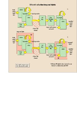
The actual implementation of a commercially viable EDFA requires the incorporation of several advanced, unique fiber-optic components in its construction to facilitate the amplifier`s optimal performance (see Fig. 1).
EDFA component features and benefits
Isolators allow light to pass in one direction but not in the reverse direction. They are placed at the output of the final amplifier and at each amplifier stage in multiple-staged amplifiers to prevent backward reflections returning from the gain stages and the final fiber output. Output reflections of the optical signal can cause significant disruption to the EDFA by triggering an uncontrolled and unstable laser feedback loop. Also, saturation at the front end of each amplifier stage is reduced between gain stages by the use of intermediate isolators that prevent reverse amplified spontaneous emission (ASE) noise propagation.
A wideband coupler can be used to split, and subsequently monitor, the essential nonwavelength-specific EDFA signal elements. A 50/50 splitter can be used to share a common pump laser and direct the split pump laser signals to the front-end WDM coupler, acting as a multiplexer, and the backend WDM coupler, acting as a demultiplexer. Additionally, tap couplers can be placed within an EDFA to monitor the incoming signal level and monitor pump laser output power, and at the final amplifier stage to monitor and control EDFA gain levels.
A WDM coupler is a wavelength-selective device that is used to combine or split signals of different wavelengths with minimum losses. It multiplexes different-wavelength optical signals from different fibers onto a single fiber or, in the reverse process, demultiplexes different wavelength signals from a single fiber onto different fibers.
In application, a wavelength-selective WDM coupler is placed along the optical signal path to mix or multiplex the pump laser light with the incoming weak input signal. The resultant mixed signal is then directed to the erbium-doped fiber length for signal amplification. The laser pump generally operates in the range of wavelengths between 1450 and 1490 nm, centered at 1480 nm; or in the range of 960 and 1000 nm, centered at 980 nm for signal amplification. The optical signal is generally in the range of 1530 and 1580 nm, centered at 1550 nm. After the amplification stage, a reverse wavelength-selective WDM coupler is placed along the signal path to then separate or demultiplex the pump laser light from the outgoing amplified output signal.
An ASE filter is placed in series and just after the erbium-doped fiber element to suppress ASE, which is the dominant source of noise in an EDFA. The ASE filter is used to improve the signal-to-noise ratio (SNR) of the output resulting from this filtering process relative to the input measured in decibels.
ASE noise results when excited erbium ions that decay to the ground energy state fail to transfer energy to the incoming optical signal. As a con se quence, a small fraction of the resultant decayed photons are emitted that have phase and direction coincident with the incoming signal; thus, they are inadvertently amplified, since they cannot be differentiated from the desired optical signal. ASE is a broadband phenomenon in that it is present over the entire gain spectrum of the amplifier. ASE filters can only filter away noise outside the signal wavelength (out-of-band noise) and cannot filter away noise within the signal wavelength (in-band noise).
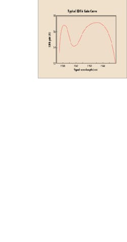
A gain-flattening filter is placed in series and just after the ASE filter to compensate for the nonlinear gain response curve of the erbium fiber amplifier. The gain curve of a typical EDFA is nonlinear over the operational wavelengths between 1530 and 1580 nm (see Fig. 2). The curve is characterized by two distinct amplitude peaks, one centered just above 1530 nm and another centered near 1560 nm. At these maximum points, there can be a 3-dB differential in gain relative to the minimum gain point centered near 1540 nm. This characteristic is one of the EDFA`s most disadvantageous performance features and necessitates the use of gain-flattening filters.
Since optical networks use multiple wavelengths propagating through multiple amplified links, it is essential that any differential in channel response be gain equalized by a gain-flattening filter on a node-by-node basis. Through this process, the cumulative gain response of the overall link, and any given node, will be flat for uniform SNR over the entire signal wavelength band.
It should be noted that gain-flattening filters are often customized to meet the unique gain characteristics of different EDFA designs.
The various components used in the construction of an EDFA can be replaced with integrated hybrid components, in which multiple functions are incorporated into a single compact device. For example, before the amplification, an isolator, tap coupler, and WDM coupler can be combined or integrated into a hybrid component (called an ITW) to perform all the functions described above for the individual components. After amplification, a tap coupler and an isolator can be combined into an integrated hybrid component called a TAPI to provide an output power-monitoring tap to control amplifier gain and facilitate the forward direction of signal flow at the output stage to inhibit output signal reflections.
There are several advantages to employing integrated hybrids in EDFA design. First, EDFA optical performance can be optimized as splicing losses and interface anomalies between single components are minimized. Further, reliability of the EDFA is improved, since the use of integrated hybrids reduces the number of internal components, splices, and connections. Also, the footprint of the EDFA can be significantly decreased, making units smaller, lighter, and more compact for protected versions. Finally, overall manufacturing labor and associated material inventory are simplified, lowering EDFA production complexity and cost. For these reasons, integrated hybrids enjoy widespread commercial acceptance.
The gain of an EDFA is proportional to the pump laser light power up to gain saturation, which is when there is no more power available from the pump laser to amplify the optical signal further. A technique to extend the gain of an EDFA is to group multiple pump lasers so amplification can be increased beyond the capability of a single pump laser source. Two techniques are available to combine multiple laser pump sources, and distinct fiber-optic components exist to implement each technique.
The first technique, called beam combining, employs the use of a beam-combiner component by which the output signal of two, and no more than two, pump lasers are polarization-division multiplexed together. The two pump laser signals must be rotated so that they are orthogonal in polarization, vertical and horizontal, for maximum power summing. These orthogonal pump laser signals can be at the same wavelength or at different wavelengths.
The second technique, called pump-combining WDM, employs fused taper technology to combine two, four, or more pumps with narrow wavelength spacing in the 1480-nm pump laser band. Here again, the pump laser signals can be at the same wavelength or at different wavelengths but are not required to be orthogonal as more than two lasers can be combined. It should be noted that there is a point at which pump combining reaches diminishing power returns, where insertion loss increases as the number of pumps increases.
EDFA component design and construction
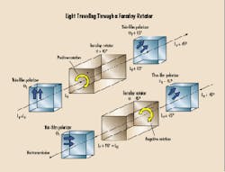
The basic principle employed in an isolator is the Faraday effect. This effect is embodied in a Faraday rotator, which is the essential component element in the isolator that inhibits the bidirectional flow of signals. Light traveling through the isolator Faraday rotator is affected differently, that is asymmetrically, depending on its original plane of polarization (see Fig. 3).
As mentioned previously, a wideband coupler is a reciprocal device that power combines multiple signals or, conversely, power splits a single signal in multiple paths. Depending on the technology used--fused, micro-optic, or waveguide--the operational wavelength band of the wideband coupler may fall anywhere between +10 and +40 nm.
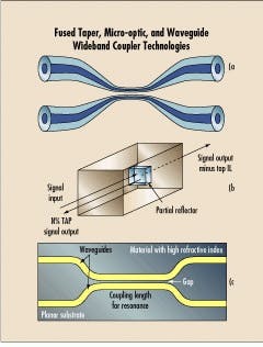
The most common commercial wideband coupler technology today is fused taper technology (see Fig. 4a). Here, singlemode fiber pairs are heated and pulled so that cladding and cores are thinned. The stretched fibers are then fused together to facilitate the signal coupling process.
Micro-optic-based couplers use internal optical reflective elements to power split an incoming signal into multiple paths (see Fig. 4b). The reflective optical elements are broadband components and can be cascaded to meet various coupler configurations. Micro-optic couplers are reliable, have excellent optical performance over temperature, and are ideally suited for integrated hybrid components.
Waveguide couplers are another technology, which, though not yet commercially significant, can be particularly useful for complex cascaded architectures (see Fig. 4c). One major challenge of waveguide technology is the manufacturing methodology used to connect input and output fibers to the planar substrate. The stabilization of waveguide substrates over temperature and the effects of long-term substrate aging need further commercial development as well. The use of twin core fibers and polished fibers are also alternative methods that remain in commercial development.
WDM couplers are constructed using different technologies. Many of these technologies are similar to those used to construct wideband couplers but have the added ability to differentiate multiple signals based on their unique wavelengths. WDM couplers used for EDFA applications are generally 3-port devices--they are used to combine and separate the 1550-nm signal from the 980- or 1480-nm pump laser light.
Filter-based WDM couplers use environmentally stable interference filters and advanced micro-optic alignment package technology to selectively control individual wavelength paths. They are widely employed (see Fig. 5a).
Resonant coupler WDM technology is an alternative technology for combining different wavelengths for transmission over a single fiber or separating different wavelengths transmitted over a single fiber onto individual fibers. These components are constructed by placing fiber cores in close proximity so there is a power transfer between fibers having different wavelengths. The final power transfer to adjacent fibers is a function of the optical signal wavelength.
ASE filters and gain-flattening filters are 2-port devices constructed with environmentally stable interference filters. These thin-film filters are integrated with collimators by advanced metal bonding technology and are housed in compact rugged packages. Thus, these components are very stable over wide operational temperature and humidity environments. ASE filters use long-pass filter elements to pass EDFA WDM signals in the 1550-nm window while blocking ASE noise, which peaks at 1532 nm. Gain-flattening filters use filter elements having EDFA inverse gain curves to flatten the double-peaked EDFA output spectrum.
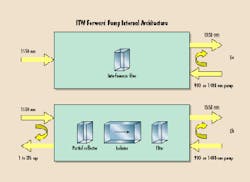
The introduction of integrated hybrids represents the next generation of passive fiber-optic components. Functionally consolidating several optical processes into a single compact device results from combining state-of-the-art packaging technology with multiple advanced optical processing techniques. As an example, Figure 5b is a simplified diagram of an integrated hybrid that comprises an isolator, a tap coupler, and WDM commonly used for EDFA applications. A partial reflector is used to construct the wideband power coupler. An isolator element is placed in series with the WDM interference filter for a forward pump architecture. The integrated hybrid component is a compact, 4-port device with ports for optical signal input and output, tap coupler output, and pump laser light input.
The basic building blocks of a beam combiner are polarization beam splitters, which separate and combine orthogonal polarized light beams. By a suitable combination and arrangement of these building blocks, the linearly polarized pump laser light beams entering the beam combiner ports are summed as orthogonal components to create a single beam with approximately 2.5 dB more pump laser power.
Pump combiners are very different in construction from beam combiners and use the technologies previously described for WDM couplers.
Key performance specs
The following specifications need to be considered when evaluating the performance of the various fiber-optic components described for EDFA applications.
Center wavelength and operating bandwidth define the wavelength region for which the optical component optimally performs in accordance with its other specifications. EDFA components typically operate in distinct windowed bands centered at the standard EDFA operational wavelengths: 980, 1480, and 1550 nm.
Component insertion loss is the difference in a signal`s output port power relative to its input port power measured in decibels. Typically, insertion loss for optical components is less than 1 dB. Insertion loss is increased for optical components having port counts greater than three, such as the integrated hybrids that employ tap couplers.
Component isolation is the difference in power between two consecutive input signals, S1 and S2, measured at port P1 in decibels. Peak isolation can lie between 40 and 55 dB depending on the component model. It should be noted that unlike insertion loss, the number of ports does not affect the component`s isolation specifications. Isolation can be increased by using double-staged components.
Component directivity is the difference in power between an input signal, S1, measured at two consecutive ports, P3 and P2, in decibels. Directivity is typically better than -55 dB.
Extinction ratio is a specification relevant to polarization-maintaining fiber-optic beam combiners and relates to the beam combiner`s ability to maintain the polarization of a signal through the device. It is the difference in power between the input signal at a fixed polarization measured at port P1 and port P2. Extinction ratio is typically 20 dB or better.
Maximum optical power is the highest signal power that can be transmitted through the component without damaging it--usually in the 300-mW range. For components that do not have epoxy in the optical path, maximum optical power can exceed 1W. Maximum optical power is a very important criterion to consider when selecting components for higher-power EDFA applications.
Future trends
EDFA optical components, like other optical technologies, are continually subject to technical improvement and innovation.
For simple 2- and 3-port devices, optical specifications will continue to improve through incremental enhancement of such characteristics as insertion loss and isolation.
Increases in integration while minimizing component footprint will be another step in the evolution of components, making their integration into EDFA equipment even simpler and more cost-effective. Components will likely be commonly integrated with gain-flattening and ASE filters to further reduce EDFA manufacturing costs and increase system reliability. The most interesting evolution of EDFA components will be further integration of control and monitoring circuitry for management of redundant protected architectures. u
Zee Hakimoglu is vice president, business development, fiber optics and integrated modules, at Kaifa Technology (Sunnyvale, CA).Fig. 5. A filter-based WDM coupler integrates a thin-film interference filter into a 3-port, environmentally stable package (a). The ITW hybrid integrates a partial reflector, coupler, isolator, and filter in an environmentally stable, 4-port package (b).
