How to check out optical amplifiers
How to check out optical amplifiers
As a result of evolving technology, the key test parameters for erbium-doped fiber amplifiers--output power, noise figure and gain--rely mainly on the application
eric malzahn
hewlett-packard co.
Because optical amplifiers are considered a relatively new technology, erbium-doped fiber amplifiers need to be performance-tested through each ste¥of their development, including the final stages of installation and maintenance in an optical link. The test specifications and methods for an immature product sector, however, remain challenging as optical amplifier manufacturers, system suppliers and network providers sort out the cost, quality and reliability issues.
Accordingly, manufacturers are monitoring fiber-amplifier quality in all product phases from initial design through actual operation. Whether they fabricate their own amplifiers or buy them from manufacturers, system suppliers have to test the amplifiers from research and development or incoming inspection through subsystem/system production to installation. Service providers, who own and use the network links incorporating optical amplifiers, must test during evaluation/ acceptance, incoming inspection and installation.
As erbium-doped fiber amplifier products and operations continue to evolve for manufacturers, suppliers and providers, the number of performance test parameters is steadily increasing. However, three key test parameters--output power, gain and noise figure--can be used to characterize basic amplifier operation. At this time, though, selecting the most critical measurement parameter depends on the application.
For example, output power becomes the most important measurement when EDFAs are used as booster amplifiers. But when these units are used as inline amplifiers to refresh signals between links, noise figure testing assumes prime consideration. This test is especially crucial in long-haul links. Noise level must be minimal because any noise in an optical amplifier is magnified by all subsequent amplifiers. High gain receives priority when the amplifiers have to be optimized as preamplifiers for signals entering a receiver.
Erbium-doped fiber amplifiers consist of an optical fiber doped with the rare earth element erbium, a pum¥laser and optical components such as couplers, isolators and connectors.
These optical amplifiers have become attractive alternatives to opto-electronic regenerators in submarine and long-distance links. Although reliable market statistics are unavailable, Hewlett-Packard estimates worldwide sales at approximately 4000 units in 1994. The prime markets are in Japan and the United States.
Depending on how fast new voice, video and data services expand, optical amplifier sales could grow to tens of thousands of units per year in a decade`s time. The amplifiers are expected to be integrated into submarine, cable-TV and terrestrial systems.
The increasing use of optical amplifiers in communications systems is predicated on two key amplifier characteristics--multiple wavelength amplification and bit-rate independence.
These amplifiers can amplify over a broad wavelength range with almost equal gain. Current optical amplifiers work within a range of 40 nanometers, around 1550 nm. The main advantage of multiple wavelength amplification is that today`s single-wavelength links will not have to be redesigned when wavelength-division multiplexing is implemented in the future. The combination of wavelength-division multiplexing transmission capability and virtually unlimited modulation bandwidth will enable optical amplifiers to markedly increase system capacity in future networks.
Bit rate-independent means today`s 2.5-gigabit-per-second links can be upgraded to 10 Gbits/sec or to higher bit rates by changing the transmitter and receiver stations.
Other amplifier benefits include high output power and straightforward design. The power level of today`s high-power EDFAs exceeds 26 decibels relative to milliwatts (or 400 milliwatts). This power level is needed to handle longer repeaterless links that use optical amplifiers as booster amplifiers. High power is also needed for cable-TV and fiber-to-the-home applications where the information from one trunk line has to be delivered to many subscribers.
The straightforward design improves repeatability and makes the optical amplifiers easy to manufacture and support.
Total output power for optical amplifiers can be measured by using an optical power meter as a receiver. In addition, an optical spectrum analyzer is needed to measure the input and output spectra to determine the signal power at selected wavelengths. Depending on whether the optical amplifier is to be measured at one or many wavelengths, the test signal source should be a distributed feedback laser or a tunable laser, respectively.
These basic test instruments allow the optical spectrum measurements of the amplifier`s input signal (distributed feedback laser or tunable laser source) and the amplifier`s output spectrum. In this setup, gain is defined as the difference between the output and input powers at the input signal`s wavelength. In reality, however, the measured signal level is not the true signal level because it contains noise.
The true signal level is the difference between the measured signal and the noise at the signal wavelength. Unfortunately, noise cannot be measured directly; instead, it has to be interpolated by measuring the noise level at two wavelengths on both sides of the signal wavelength. True gain can then be calculated from the true output and input signal levels. In practice, however, this correction can be ignored because the effect of noise on gain results is negligible.
Noise figure measurement is the most complex test for an optical amplifier. It defines the degradation in the signal-to-noise ratio by comparing the amplifier`s input and output signals.
The prerequisite tools for measuring noise figure are a test signal source and a photodetector possessing minimum shot noise (a noise caused by quantum effects). Moreover, the photodetector must have a quantum efficiency of 1 and must not exhibit thermal noise.
The total noise figure consists of five elements:
Signal shot noise at the receiver
Amplified spontaneous emission shot noise at the receiver
Noise caused by heterodyne mixing of the amplified spontaneous emission with the signal
Noise caused by the amplified spontaneous emission mixing with itself
Multiple interference noise caused by internal reflections among the amplifier`s optical components such as isolators, couplers and pum¥laser
The two mainstream test methods for measuring noise figure involve optical or electrical techniques. To perform electrical tests, a spectrum analyzer, a calibrated photodetector and a low-noise optical source are needed.
A comparison of noise figure measurements performed by the two test methods shows both are capable of delivering the same results. In practice, though, it is difficult to achieve ideal conditions. Which measurement method is better depends on the application.
In general, if the optical amplifier is viewed as a black box, and there is no need to distinguish among different sources of noise, the electrical test method is adequate. This test method is used mostly by service providers.
On the other hand, optical test methods tend to be more accurate when performance data on the amplifier`s internal components is needed. This test method is typically for optical amplifier researchers and manufacturers.
In practice, though, optical test methods can distinguish different noise sources and deliver higher accuracy. Two important optical test methods include the amplified spontaneous emission interpolation method and the polarization extinction method. Choosing the relevant method depends on the application.
The amplified spontaneous emission interpolation test method works at higher speed and lower cost than the polarization approach because a polarization controller is not needed. However, the polarization extinction method is more accurate.
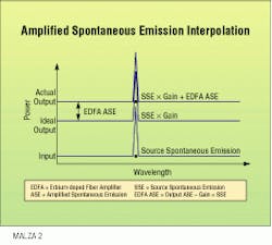
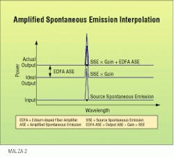
Noise figure can be measured by means of the amplified spontaneous emission interpolation method using the aforementioned basic measurement setup. The source spontaneous emission is measured as the noise level of the input signal. The gain measurement described previously and the measurable output noise level are the sum of the amplified source spontaneous emission and the amplified spontaneous emission. In this manner, the noise figure of the optical amplifier is directly calculated.
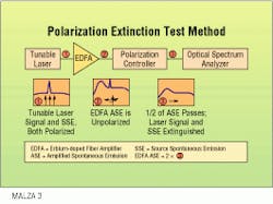
The second optical test method is the polarization extinction method. This takes advantage of the fact that the tunable laser signal and the source spontaneous emission are polarized; the amplified spontaneous emission, however, is unpolarized. Because the input signal remains polarized even after amplification, the tunable laser signal and the source spontaneous emission can be eliminated by means of a polarizer. But half the amplified spontaneous emission still passes through the polarizer because it is unpolarized. Therefore, the amplified spontaneous emission can be calculated by doubling the measured spectrum.
Measuring the gain and the amplified spontaneous emission yields all the data factors to calculate the noise figure. The first factor is shot noise, which is the reciprocal value of the gain. The second factor comes from the heterodyne mixing between the signal and the amplified spontaneous emission. The last two factors--amplified spontaneous emission-to-amplified spontaneous emission mixing and multiple interference noise--can be ignored because they barely affect the calculation.
Automatic test systems
In practice, the basic measurement setu¥used to perform erbium-doped fiber amplifier testing is a slow, manual process that does not yield accurate results. In its place, a higher performance solution is achieved via a fully automatic operating optical amplifier test system that supplements the basic measurement setup.
An automatic test system also contains a tunable laser as a source and an optical spectrum analyzer as a receiver. In addition, a lightwave multimeter continually and more accurately monitors input and output power.
To measure higher amplifier input power, a booster erbium-doped fiber amplifier, an external attenuator and a polarization controller are incorporated. Known as a booster system, this test system can also measure polarization-mode dispersion and polarization-dependent gain.
Automatic test systems are controlled by a workstation and run under Unix software. The hardware/software combination allows the integration of the automatic test system into a local area network, thus providing access to a production database or remote measurement inventory. These test systems are used mainly by optical amplifier manufacturers, that need high throughput, high repeatability and low uncertainty.
Furthermore, amplifier manufacturers also require a high yield to reduce costs and tight specification bandwidths to gain competitive advantage. To reduce the time to market and minimize costs during the learning curve, the amplifier product`s ramp-u¥must be quick. Such a major test equipment investment--the price of an automatic test system starts at approximately $220,000--must naturally offer an upgrade path for enhancements.
Future amplifier testing
Two main trends in optical amplifier testing involve 1300-nm praseodymium-doped optical amplifiers and wavelength-division multiplexing. Both technologies are in transition from the research and development stage to production status.
Testing optical amplifiers at 1300 nm requires dedicated lightwave instruments, such as a 1300-nm tunable laser source. The measurement methods for 1330 and 1550 nm are the same.
Characterizing optical amplifiers for wavelength-division multiplexers is still under investigation. One approach uses the same test signals as employed in the final link; for example, coupling two, four or more distributed feedback lasers and using them to generate the test input signals. The tested optical amplifier will almost certainly behave the same way in the real world. On the down side, though, this approach is expensive and inflexible. For example, changing the wavelength calls for replacing a laser.
A more sophisticated solution would be to use two lasers--one distributed feedback laser to drive the optical amplifier to saturation and one tunable laser source to act as a probe laser. This setu¥is less expensive and more flexible than the first approach. However, the theory of testing optical amplifiers for wavelength-division multiplexing applications is in its infancy and involves numerous challenges. q
Eric Malzahn is product marketing engineer at Hewlett-Packard`s Boeblingen Instruments Division in Germany.Another measurement of the noise figure of an erbium-doped fiber amplifier takes advantage of the polarization of the tunable laser signal and the amplified source spontaneous emission. Because the amplified spontaneous emission is not polarized, one-half the amplified spontaneous emission signal passes on to the optical spectrum analyzer.


