Networking firm builds "new-generation" nationwide fiber-optic network
Networking firm builds "new-generation" nationwide fiber-optic network
Determined to differentiate itself from established carriers, Williams will rely on new architectures, equipment types, and fiber in its network construction.
Mark Allen and Chris Hamilton, Williams Network
Laura L. Hluck, Corning Inc.
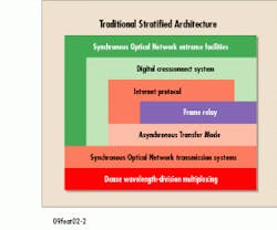
The explosion in demand for bandwidth has been fueled by the rapid growth in the Internet and bandwidth-hungry multimedia-oriented applications like videoconferencing and high-definition television. To meet this demand, Williams Network is building a new nationwide network different from that of traditional carriers (see Fig. 1). The Williams Multi-Service Network is designed to provide performance-driven products that include frame relay, Internet protocol (IP), Asynchronous Transfer Mode (atm), and voice services, while simultaneously providing traditional time-division multiplexing (tdm) services such as DS-3 (44.736 Mbits/sec) and DS-1 (1.544 Mbits/sec) on the same physical platform.
Leveraging this new architecture allows Williams to further streamline internal cost structures over existing telecommunications service providers. The key technologies for the Williams network are high-capacity multiservice atm backbone switches, an end-to-end dense wavelength-division multiplexed (dwdm) platform, and a nationwide network of fiber-optic cable.
High-capacity backbone
In addition to advanced network design, hardware, and optical fiber, minimizing the number of different platforms that must be operated to deliver network products is critical to the Williams network architecture. Competing carriers offer their services on an array of separate platforms (see Fig. 2). DS-3 (44.736-Mbit/sec) and DS-1 (1.544-Mbit/sec) private-line services are delivered using digital crossconnects (dcss) layered over a Synchronous Optical Network (sonet) transmission system. IP services are generally overlaid on the dcs system using a separate network of routers. atm and switched voice networks are individually handled in a similar manner to meet the requirements of each service. As the amount of data traffic continues to grow in proportion to voice and private-line services, the inefficiency associated with multiple overlay networks begins to take its toll.
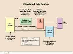
The Williams network architecture is designed to be "vertical," as opposed to the "stratified" architecture of the typical carrier. As shown in Figure 3, each service has direct access to the fiber-optic infrastructure. Direct access has become possible with the availability of high-speed interfaces on the atm and IP switching equipment.
To eliminate the need for multiple layers in the network, Williams is transporting all tdm and data traffic as atm cells through the backbone network, which allows all network monitoring and provisioning to be performed from a single platform. The provisioning process for turning up a circuit through the network is now much simpler--the system automatically chooses the most optimal route through the network after the user enters the desired endpoints via a "point-and-click" interface. In traditional networks, services must be turned up through dcs systems that require commands to be issued to several different elements across the network. These dcs systems also consume a large amount of physical space and power in the points of presence of the traditional carriers.
Another unique feature of the network is its management, provisioning, and billing system which enables Williams to to implement usage-based billing for its data services. The billing system allows circuits to be deployed in a matter of minutes rather than days, as in the traditional carrier networks. The key piece of hardware behind this is Ascend`s GX550 atm switch, a 25-Gbit/sec switch that includes OC-48 (2.5-Gbit/sec) trunk interfaces. By using wavelength transponders, the OC-48 trunk interfaces on the atm switches will be connected directly to the wdm multiplexers, thereby bypassing the sonet transmission systems. Williams will improve network transparency in the future by optical add/drop multiplexing directly from the amplifiers and using sonet-free regeneration. This will eliminate redundant components and protection schemes and significantly reduce costs.
For transmission gear, Williams chose Nortel`s OC-192 (10-Gbit/sec) system for delivering very high bit-rate sonet private lines. This hardware provides Williams with the capability to offer OC-48, OC-12 (622-Mbit/sec), and OC-3 (155-Mbit/sec) circuits from an integrated platform. Nortel`s system includes a procedure for management of its bidirectional erbium-doped fiber amplifiers (edfas). The Nortel bidirectional amplifiers allow the fiber to be more fully utilized since two, rather than four, fibers are used to achieve a protected span. The edfas are currently capable of amplifying 16 wavelengths, or channels, with each wavelength carrying 10 Gbits/sec of traffic--effectively delivering a total capacity of 160 Gbits/sec per fiber. Through deployment of next-generation fiber and advanced edfa systems, the network will have even more capacity--32 wavelengths, or 320 Gbits/sec, on a single fiber.
Restoration requirements
The ability to restore the network in an efficient, yet cost-effective manner is a critical requirement for the new Williams network. Therefore, the network is being built in a mesh, rather than the typical ring configuration, to provide protected capacity while maintaining low cost.
Since Williams can locate much of its cable along pipeline rights-of-way, the need for restoration due to cable cuts is significantly reduced. Pipeline rights-of-way are very secure and much less susceptible to service interruptions when compared to aerial cable or cable adjacent to railroads.
However, if restoration were to be required in the network, the atm network described above has a built-in rerouting capability that can automatically locate an alternative path for circuit traffic in the event of a cable cut or service interruption. Unlike a sonet ring architecture, the mesh network is optimized to fully use all of the protection bandwidth. Traffic can be provisioned with priorities so that an array of quality-of-service levels can be delivered. Thus, the statistical multiplexing offered in the atm network fully uses the available bandwidth while maintaining the highest possible network availability.
Fiber specifications
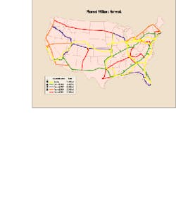
The foundation of the Williams network will be the installation of 32,000 mi of fiber-optic cable by the end of 2001. For the initial long-haul builds, Williams selected Corning`s smf-ls fiber, which is a non-zero dispersion-shifted fiber (nz-dsf) first introduced in 1994. This nz-dsf was developed specifically for high-capacity, long-distance wdm systems, and has enough dispersion to suppress 4-wave mixing in the edfa signal band. The fiber`s dispersion, however, is also small enough to allow OC-192 transmission at long uncompensated, or terminal compensated, distances.
As well, Williams recently began to deploy Corning leaf optical fiber, a non-zero dispersion-shifted fiber with positive dispersion across the edfa band. The fiber is designed to transport multiple wavelengths at OC-192 through its 72 micron2 effective area, low-loss bending performance, spliceability, and low polarization-mode dispersion values.
Since nonlinearities are a key limitation in the performance of high-data- rate systems such as those employed in the Williams network, reducing these linearities has become a top consideration for today`s network planners. System nonlinearities result from high input powers, the presence of multiple channels at narrow channel spacing, and the longer distances that are now achievable with edfas. The nonlinearities that affect transmission performance include stimulated Brillouin scattering, stimulated Raman scattering, self-phase modulation, cross-phase modulation, and 4-wave mixing. In general, nonlinearities are proportional to
where n2 is the nonlinear index coefficient, P is the input power, L is the overall effective length of the transmission system, and Aeff is the fiber`s effective area.
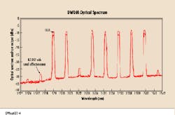
Although dispersion manipulation can lower some nonlinear effects, namely 4-wave mixing, increasing a fiber`s effective area is the only fiber method available to reduce all nonlinear effects and improve system performance for long-haul transport. Effective area is the cross-section of the fiber where the light propagates. A larger effective area allows more power and channels to be inserted into the fiber before nonlinear effects can degrade the system operation. The larger effective area reduces the light intensity in the fiber, which results in lower nonlinearities. The result is a high-speed transmission network that can transmit over longer distances with higher signal-to-noise ratios, lower bit-error rates, better overall system performance, and upgrade flexibility. As dwdm equipment improves and system operation expands into the L-Band, or the window between 1570 and 1650 nm, the high optical-power density and nonlinearities resulting from so many channels being lit on a single fiber may challenge fibers with a smaller effective area (see Fig. 4).
Dispersion compensation may be required for some of the longer span designs in the Williams network. When required, small amounts of compensation can be added to the terminal and/or receiver sites to keep the deployment simple and easy to maintain. The commercially available dispersion-compensation modules that will be used with the leaf fiber were initially developed for use with standard singlemode fiber, but will require no modification for use with leaf fiber.
As part of its evaluations, Williams successfully conducted splicing studies in simulated field conditions on the leaf fiber. The fiber was cabled in Siecor Corp.`s altos cable, a loose-tube cable designed for outside plant telecommunications applications. The splicing equipment used was commercially available splice gear (see table).
In with the new
Williams is building a new network unencumbered by legacy equipment and allowing the deployment of the latest technology. The network architecture consolidates multiple services on a common platform and reduces the management inefficiency experienced by other carriers who operate multiple parallel networks overlaid on a network of narrow-band crossconnects.
In the future, Williams will continue construction of its data-centric architecture, and will have installed over 32,000 mi of fiber by the end of 2001 as part of its network. Because wdm will be the convergence layer, Williams is moving toward an architecture where there is an open interface between the wdm and the atm, sonet, and IP network equipment. As broadband sonet and optical switches become available, bandwidth will be provisioned and protected as large "pipes." These switching devices will include flexible network restoration where optical bandwidth can be configured and efficiently managed. q
Mark Allen is senior staff engineer for technology development and Chris Hamilton is lead engineer, fiber and optical engineering team, at Williams Network (Tulsa, OK). Laura L. Hluck is a senior market development engineer at Corning Inc. (Corning, NY). They can be reached at [email protected], [email protected], and [email protected], respectively.Fig. 4. The optical spectrum of dwdm transmission through a leaf fiber and conventional nz-dsf is shown here. Seven OC-192 wavelengths, each spaced 100 GHz apart with powers of 10 dBm/channel, were launched into 80 km of both fibers.


