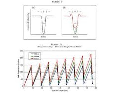
Figure 1: Transmission pattern (...101...) showing (a) back-to-back and dispersed (b) signals for standard transmitter (red) and DTOM (green). Sampling threshold (horizontal line) shows large penalty for standard transmitter, recovered (arrow) with DTOM.
Figure 2: Dispersion map for 8-span transmission system using standard single-mode fibre and DCF. Net accumulated dispersion is largest for 1570-nm edge channel, at 900 ps/nm.
By BRIAN SCHREDER, BILL SIPOWICZ, and JASON STARK
Kodeos Communications
Over the past few years, service providers have deployed high-channel-count DWDM systems, expecting that they could fill the equipment to capacity as extra bandwidth was needed on specific routes.
But now the economic downturn is forcing them to minimize the cost of upgrading each network bottleneck, so they are focusing on purchasing additional line cards to finish populating partially filled chassis, lighting the edge channels on the extreme ends of the C-band, and adding channels at narrower spacing to mostly filled network links.
Dispersion-tolerant optical modules (DTOMs) employ advances in optical transmission technology to solve these problems. Equipment vendors can use DTOMs to deploy systems with fewer electrical regenerators, longer dispersion-limited links, and double-density wavelengths that increase network capacity.
Optical transmission advances
Since 1998, new optical transmission technologies have reduced system cost and increased transmission efficiency. As the advantages of silicon process scaling become available to the high-speed optical systems engineer, technologies common in other communication systems are now being implemented for optical transmission.
For example, terrestrial equipment companies have begun to employ forward error correction (FEC)--the first application of advanced signal processing technology to optical transmission--to provide reliable transmission at steadily lower values of the optical signal-to-noise ratio (OSNR). System engineers had been hesitant to adopt the technology because physical solutions using bulk optics and brute-force approaches worked satisfactorily in the past. But FEC's lower cost and higher performance have begun to drive implementation in system equipment.
However, the gain provided by FEC, measured in terms of decibels of OSNR margin at a specific bit-error rate (BER), is at the expense of additional overhead, requiring a higher transmission rate. For example, at an output BER of 10 -15, a 6-dB coding gain is obtained using an FEC code with 7% additional overhead (as specified by ITU-T G.975). This, and its associated increase in modulation bandwidth, leads to an increase in dispersion penalty that partially offsets the benefits from the FEC coding gain.
DTOMs alleviate this compromise through several emerging signal processing techniques. On the transmit side, line coding--which conditions signals prior to launch--keeps the transmission eye open over greater distances and makes the overall system more tolerant of dispersion. On the receive end, equalizers dynamically adjust to changing line characteristics and work synergistically with line coding. Also, spectral shaping and narrow optical filters yield higher spectral efficiency for greater bandwidth utilization.
Chromatic dispersion
Chromatic dispersion is the most significant limiting factor in long-reach 10-Gbit/sec applications. The effects increase quadratically with modulation bandwidth and are, for example, 16 times worse at 40 Gbits/sec. Due to this, a signal pulse launched into a fiber is distorted when it arrives at the receiver, making it harder to distinguish a '0' (space) from a '1' (mark), and ultimately leading to transmission errors.
For example, consider an isolated space (Figure 1). In standard on-off keying, the field from the marks will spread into the time slot of the space, leading to intersymbol interference (ISI). This smearing from the surrounding marks raises the bottom of the transmission eye, bringing the received level of the space close to the sampling threshold and diminishing the OSNR margin.
Transmission fiber and dispersion compensation elements are used to create a dispersion map, which determines the accumulated chromatic dispersion over the length of a network route. Typically, it is implemented using dispersion compensating modules (DCMs) at amplification sites. Here, an erbium-doped fiber amplifier (EDFA) is followed by a DCM, with a subsequent EDFA required to offset losses in the DCM.
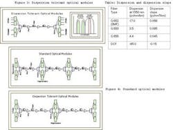
The DCMs are not perfect, however, and the amount of dispersion compensation varies over the wavelength band, due to the dispersion slope mismatch of the dispersion compensating fiber (DCF) used in constructing the DCM (Table 1). As a result, each wavelength channel encounters a different amount of accumulated dispersion, in accordance with the dispersion map (Figure 2). This compensation scheme is applied on a per-fiber basis, with channels at the edge of the wavelength band suffering the largest amount of accumulated uncompensated dispersion.
The amount of dispersion in the network has a direct effect on the engineering rules for optical transmission systems that carriers and their systems partners establish to ensure the required level of system reliability. The quality of the received signal, degraded by dispersive propagation and the noise generated by loss-compensating optical amplifiers, is ultimately limited by impairments associated with nonlinear distortion. Given these limitations, penalties are allocated to minimize cost.
For a given amplifier spacing, penalties associated with amplifier noise accumulate in proportion to the length of the system. Penalties remain low for moderate amounts of dispersion and then rise rapidly when the penalty reaches a level of 1-2 dB. As a result, systems are typically designed to achieve a fixed level of dispersion penalty, after which the signal must be received and regenerated. Long-haul fiber spans that reach the dispersion budget limit are ultimately terminated by regenerators.
DTOMs can greatly ease the problems associated with dispersion, both in terms of setting the dispersion map and designing the network to achieve maximum utilization of bandwidth and greater transmission range. System providers can therefore offer improved economics in a variety of applications.
DTOM applications
With service providers wanting to keep their capital equipment costs low, a problem arises when heavily loaded network links are nearing full capacity. Traditionally, service providers had two options: they could either make "spaghetti" out of their network by routing traffic between two adjacent nodes around the heavy traffic link, or they could add a green-field build at significant cost.
A new third option is now available by replacing standard transmission modules with a DTOM that enables the remaining links to carry double the network capacity. A double-density DTOM launches two channels into the wavelength band allocated for the single channel output of a standard module (Figure 3). This will enable, for example, a 40-channel DWDM system that currently has 32 wavelengths in service to add 16 more instead of the anticipated eight.
A key issue with this doubling is that optical amplifiers have a fixed saturation power. To take this into account, double-density wavelengths must launch 3-dB less power per channel, so that the two together launch the same power as a single wavelength at the original spacing.
To recover the 3-dB power penalty, a higher-overhead FEC device is used to provide the required 3-dB of margin over the ITU-standard 7% overhead FEC. The higher overhead produces a higher dispersion penalty that can be removed by using a DTOM. Double-density wavelengths are provided through advances in signal processing and line coding, while maintaining the original engineering rules. The chassis is inexpensively upgraded with the more advanced line card technology to create a cost-effective architecture.
DTOMs can also lower network deployment costs when increasing demand on a specific link necessitates the use of extreme edge channels, which suffer from the greatest dispersion penalty and typically determine the overall system reach. The high level of dispersion encountered can prevent these wavelengths from being successfully deployed. DTOMs can be used to recover reliable transmission in edge channels that exhibit marginal performance.
DTOMs also encourage long reach and decrease the need for electrical regenerators. Using a commercial long-reach module, a 1.5-dB dispersion penalty corresponds to 850 ps/nm of dispersion. By contrast, new DTOMs can transmit up to 1,300 ps/nm without dispersion penalty. So the 1.5-dB of margin formerly reserved for dispersion penalty can be allocated to OSNR margin, to achieve about 1.5 times the number of amplified spans allowed before signal regeneration (Figure 4). The result is a system that has one-third fewer regenerators for the same overall transmission distance.
As the preceding network-build example illustrates, DTOMs permit up to 50% more optical amplifier sites to be traversed before electrical regeneration. This means that many long-haul network links will not need electrical regeneration at intermediate nodes and can be upgraded at substantially lower cost. Multiple electrical regeneration cards can be replaced with a lower-cost optical amplifier module.
As fiber moves closer to the end-user, metro and regional networks are growing longer and requiring more add/drop nodes. DTOMs can save costs here as well. In many metro and regional applications, traffic is aggregated for transmission over the long-haul portion of the network. Signals on an optical ring have to traverse the ring in opposite directions (for working and protection channels). This typically involves a short-reach link (work), as well as a long-reach link (protect) that traverses the long way around the ring.
The protect wavelength must bypass several optical add/drop nodes that are aggregating traffic onto other wavelengths. Even though the wavelength is only bypassing them, there is a power loss associated with the wavelength splitting at each node. By using higher-overhead FEC, the power penalty can be recovered. Once again, the increasing dispersion penalty associated with higher-overhead FEC can be offset by the use of a DTOM. Metro and regional networks can thus be designed to reduce electrical signal regeneration.
Summary
The long-reach market in 2002 will be dominated by adding line cards to existing systems rather than deploying new systems. The use of line cards that have superior performance and use the existing infrastructure better will be valuable to carriers trying to keep their network costs down. The new DTOMs are modules that bring these kinds of enhancements to optical transmission systems.
DTOMs transmit optical signals that are highly resistant to chromatic dispersion, leading to applications where the number of electrical regenerators may be reduced or where extra edge channel slots may be populated.
DTOMs also transmit signals that occupy less optical bandwidth, enabling double-density channels that extend the useful life of existing systems. Finally, the DTOM's line coding is complementary to FEC techniques. Used together, they deliver significantly more OSNR margin to the system integrator, leading to more flexible engineering rules, better system performance, and lower costs to the end-user.
Brian Schreder is vice president of marketing, Bill Sipowicz is vice president of business development, and Jason Stark is chief technology officer at Kodeos Communications of South Plainfield, NJ. They may be reached via the company's Web site at www.kodeos.com.
Figure 3: Two client signals at 10 Gbits/sec are transmitted by each DTOM through a standard 10-Gbit/sec channel. Double-density transmission is transparent to transport link, which retains legacy engineering rules.

