Optical-amplifier architectures based on ultra-fast optical switches
The most common elements in optical networks are optical amplifiers (OAs), particularly erbium-doped fiber amplifiers (EDFAs). Together with DWDM technology, OAs enable high-capacity transmission in ultra-long-haul (ULH) and long-haul (LH) terrestrial networks. In these networks, the main role of the OA is to overcome signal loss when the signal is propagating in an optical fiber (i.e., fiber loss).
OAs are often essential elements in metro networks as well. Although shorter distances are required, OAs are still needed to accommodate for insertion loss from the use of optical add/drop multiplexers (OADMs) and other optical-network elements.
The need for optical amplification is spurring the development of numerous types of OA architectures based on fiber and waveguide technologies, which are classified by the dopant (e.g., erbium) and the glass host (e.g., silica) used. The actual design of an OA depends on the amplifier type and its intended application. The design of EDFAs or hybrid EDFA/Raman amplifiers for LH applications differs widely from the architectures of semiconductor OAs, or compact EDFAs applied in metro applications.
A significant amount of work is underway to assess the benefits of introducing new optical-switching technology to telecommunications networks.1 Adding new capabilities such as variable optical attenuation and optical multicasting into the optical-switching component, while increasing the switching speed, offers several advantages. Introducing this new breed of optical-switching component into the OA enables many applications.
A reference architecture applicable to EDFA line amplifiers for LH applications serves as common ground for discussion. This design is applicable to many amplifier types, and the described concepts can easily be adapted to different explicit amplifier designs. The design is based on a two-stage amplification approach. In this manner, a low noise figure, high-gain amplifier is achieved.
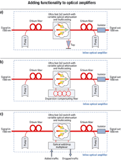
By introducing different components or subsystems between the two gain media, additional functionality can be incorporated into the amplifier. The introduction of a variable optical attenuator (VOA) can lead to an amplifier with increased dynamic range. The integration of dispersion-compensating fiber allows cost-effective management of the dispersion map with minimum penalty to the optical-signal-to-noise-ratio (OSNR) budget. The addition of an OADM allows for adding and dropping of traffic at the amplifier node.
Since OAs are the most common element in optical networks, their resilience plays a major role in network reliability. The failure of a single amplifier in a DWDM link usually results in protection switching for multiple channels as the entire fiber bandwidth along the link is rerouted. As such, increasing OA resilience to critical failures that prohibit the use of a given link is of immense importance. For less critical failures, which cause only degraded performance but not full link failure, it is necessary to be able to service these amplifiers while they are in operation carrying live traffic. The introduction of next-generation ultra-fast switches with variable optical attenuation can increase amplifier resilience to critical faults and allow in-service maintenance of these systems.
Proactive in-service maintenance of amplifiers is desirable to carriers because of the huge economics at play in high-capacity LH/ULH networks. Even with recent price declines, a network link carrying 200 Gbits/sec of traffic can easily generate $10,000-$20,000 of revenue per hour. By performing maintenance without taking network elements out of service, carriers not only ensure that revenue stream, but they also avoid any penalties associated with not meeting service-level agreements.
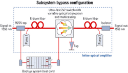
When a noncritical fault occurs in an OA, it's necessary to service the amplifier while it is fully operational. That is done through bypassing the faulty amplifier (or subsystem), rerouting the connection through an appropriate backup system, and performing maintenance operations on the line amplifier without affecting the link's traffic.Figure 1 shows how an ultra-fast switch is used in the bypassing operation. The use of a switch with <500-nsec switching enables the entire bypass operation to be performed with only a 500-nsec disruption of traffic. This disruption is short enough to avoid transients in amplifiers further down the link. The phase-locked loop of the receivers at the egress of the link may still be affected, but they're locked fast enough to avoid protection switching. The configuration shown in Figure 1 is easily adapted to perform the bypass operation on only a part of the OA.
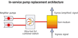
It's also possible to use the inherent multicast functionality found in some next-generation switches to add optical taps into the system without incurring additional losses. Figure 2 illustrates some of these concepts. In this design, the backup system must compensate for the added penalty to the OSNR incurred by using a 5% tap as the test access. An isolator is used to avoid the amplification of reflected light and the possibility of a resonant cavity. Tap couplers with photodiodes are usually included to monitor the input, output, and reflected optical power levels. These measurements can be used as feedback for adjusting the pump-laser power and to initiate an automatic shutdown if the output fiber is broken or disconnected.Figure 3 is a reference design that allows servicing of faulty pumps without disturbing the OA's operation. The principle of the design is to use the switching and reverse multicast functionalities of the optical switches to isolate the defective pump from the gain medium. Two pumps are connected to the gain medium through an optical switch. The switch combines the powers from both pumps using reverse multicast. Once a fault is detected in one of the pumps, the switch is set to connect only a single pump to the gain medium. Since the reverse multicast has an inherent 3-dB loss on each pump, once the switch connects only a single pump, the output power remains constant. During the switching time (sub-500 nsec), a minor transient may occur in the OA. Its effects, however, can be limited by using a hold-off timer, in which case the effect on the network is also limited. Finally, since the defective pump is no longer connected to the gain medium, it can be serviced without affecting the link.
Because amplifier nodes are the most common nodes in transport networks, it is beneficial for service providers to use an amplifier design that can support changes in network traffic patterns. After an amplifier is installed, service providers may want to add or drop traffic from that same node. They may also need to add dispersion compensation to the amplifier or even change the amount of amplification provided. By integrating an ultra-fast switch with variable optical attenuation and multicast functionalities into the OA, it's possible to futureproof the network design should any of these circumstances arise.A generic architecture that can be used to add functionality to an OA is shown in Figure 4a. Here, an ultra-fast switch is integrated into the amplifier architecture where it can play numerous roles. Figure 4b shows how to provide dispersion compensation within the amplifier node and Figure 4c illustrates the introduction of reconfigurable OADM (ROADM) functionality. In some cases, such as upgrading from an amplifier node to an ROADM, the addition of the new function can be performed in-service with minimal effects on the network. The option of midstage access is important because it can accommodate for the insertion loss of the dispersion-compensating unit or the OADM unit and offers the capability to separately control the gain of dropped and added channels.
Another point worthy of discussion is the gain dynamics in doped-fiber amplifiers consisting of an optical fiber that has a core doped with erbium. Light from external-pumping semiconductor lasers is coupled into the fiber, exciting the erbium atoms. Optical signals in the C- or L-bands entering the fiber stimulate the excited erbium atoms to emit photons at the same wavelength as the incoming signal resulting in optical amplification. The transient gain dynamics in such amplifiers have been studied intensively in connection with sudden channel addition or removal.3 Here, the duration of power transients is important since it may induce temporary performance degradation. The transient duration is connected to the population dynamics of the dopant ions and may be much faster than the relaxation time of the ions. Nonetheless, in silica-based EDFAs, the transient duration can easily exceed 1 msec.
It is important to note that both the OSNR and bit-error rate (BER) change during the gain transient changes. This situation is almost inevitable during an add/drop operation.4 The worst BER (and lowest OSNR value) occurs at the channel power undershoot, which follows immediately after a channel add event. Furthermore, in such a scenario, the BER may exceed 10-7, which is unacceptable statistically. This period of time is on the order of 10 msec. A submicrosecond transient control mechanism, which may be obtained via an ultra-fast switch with an integrated variable optical attenuation capability, is needed to avoid BER/OSNR changes. That will allow for amplifiers to exhibit gain transient changes without affecting the performance of the network.
Ultra-fast switching in OAs enables increased resilience to critical faults, better maintenance, and new functions. It's possible to perform these switching operations inside an amplifier system with minimal effect on the live communications link in all applications. Finally, it's often advantageous to replace tap couplers with photodiodes with an ultra-fast optical switch that supports integrated multicast and variable optical attenuation capabilities to allow for monitoring and quick adjustments.
Roy Appelman is director of systems engineering and Gal Shabtay is manager of algorithms and simulations at Civcom Inc. (Petach Tikva, Israel). Mike Myshrall is Civcom's vice president of marketing and business development, North America, based in Reston, VA.
- Z. Zalevsky, D. Mendlovic, E. Marom, N. Cohen, E. Goldenberg, N. Konforti, A. Shemer, G. Shabtay, U. Levy, and R. Appelman, "Ultrafast all-optical switching," Journal of Optical Networking, Vol. 1, p. 170 (2002).
- S. Pawlik, B. Mayer, S. Mohrdiek, I. Jung, B. Sverdlov, N. Lichtenstein, N. Matuschek, and C. Harder, "Highly efficient 980 nm single mode modules with over 0.5 Watt pump power," OFC Technical Digest, WC1-1 (2001).
- A.K. Srivastava, J.L. Zyskind, and J.W. Sulhoff, "EDFA transient response to channel loss in WDM transmission system," IEEE Photonics Technology Letters, Vol. 9, pp. 386-388 (1997).
- W.S. Wong, H.S. Tsai, C.J. Chen, H.K. Lee, and M.C. Ho, "Novel time-resolved measurements of bit-error-rate and optical-signal-to-noise-ratio degradations due to EDFA gain dynamics in a WDM network," OFC Technical Digest, ThR4 (2002).


