Telecommunications industry needs have spurred developments aimed at significantly reducing the costs of optical infrastructure.1 Central to this aim is the elimination of unnecessary optical-electrical conversions. The highly scalable nonblocking all-optical crossconnect (OXC) is destined to be a key component in this elimination and hence deployed in future networks.
In addition, future OXCs must handle not only fiber-to-fiber switching, but also increasingly more complex functions, including multiplexing/demultiplexing, add/drop, and channel equalization. Due to advantages in size, cost, power, and scalability, these systems will occupy a place in the telecom network where conventional SONET-based switches and even advanced optical-electrical-optical (OEO) switches are not cost-effective.
One of the fundamental carrier requirements of large OXC switches is long-term connection reliability. Here, a reliable connection is defined as a connection meeting all performance requirements for any allowed input signal under all operating environments over the life of the connection. Environmental conditions include temperature extremes, shock, vibration, and humidity. Performance and environmental test conditions are defined in documents published by Telcordia Technologies2,3 and often made more stringent in customer specifications. Numerically, carriers demand bit-error rates below approximately 1×10-12 with system availability above 99.999%.
Micro-electromechanical systems (MEMS) are widely accepted as the technology to enable large scaling, high optical performance, and the needed cost reductions in telecom optical switching. The existing optical infrastructure built around OEO switching, SONET, and next-generation SONET has established the reliability threshold that new equipment must meet or exceed.
We'll explore technology and engineering design approaches to alleviate connection reliability concerns in MEMS-based OXC systems. More specifically, we treat an OXC as an interfaced collection of subsystems and analyze engineering designs and trades to ensure the reliability of each subsystem. That results in an OXC system sufficiently reliable for significant telecom deployment.
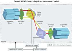
A MEMS-based OXC system comprises optics, MEMS mirrors, the mirror drive system, packaging, and a system controller (see Figure 1). The optics subsystem functions to couple light from a given input fiber into a corresponding output fiber with a minimum coupling loss. The optical path involves collimation by a microlens element reflecting off two MEMS mirrors, then focusing into a predetermined output fiber. Two MEMS mirrors are necessary to ensure that the light is coupled into the acceptance cone of the desired output fiber.The MEMS mirror subsystem reflects light from a given input fiber into a given output fiber, while the MEMS mirror drive subsystem controls the exact mirror pointing angle. The packaging subsystem includes the hermetic optical housing and the electrical interfaces to the MEMS mirrors. The optical housing includes the fiber blocks, component support structures, temperature control, and shock/vibration isolation.
The system controller is responsible for making the correct connections within an allocated time. It is also responsible for connection optimization, system performance tracking, and environmental controls.
Connection reliability of the optics subsystem involves an optical layout robust to changes in the environment—temperature, shock, and vibrations. The most sensitive section of the optical path is the section between the fiber tips and microlens array, because a small movement here translates into a large movement of the beam across a MEMS mirror.
The alignment and stability of this section is critical to the reliability of the optical-path subsystem. Fortunately, these environmental concerns can be easily mitigated by using a quasi-athermal design, stabilizing the temperature, and isolating/damping the housing.
High availability of the system controller's electronics and its associated software is accomplished using redundancy. Several redundancy schemes can be used for the electronic modules. These schemes are all well understood from other electronic systems and not specific to MEMS or OXCs.
A MEMS-based OXC adds the first-ever moving part to a telecom system that historically has been moving parts-free. As such, the reliability of the MEMS mirror is immediately suspect. MEMS mirror reliability includes mechanical failures—in reality, that is but one failure mechanism.
MEMS mirror reliability also includes the high-reflectivity mirror coatings, mirror distortion, and angular pointing shifts that can be the result of high-incident optical power or other environmental effects like temperature, shock, and vibrations. In the area of mirror actuation, edge charge effects play a significant role in reliability. These failure mechanisms are addressed in detail here, as two mirror architectures are compared and contrasted.
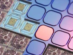
MEMS may be fabricated in one of two fundamental process technologies: bulk and surface micromachined. Bulk micromachining involves etching away silicon from a substrate. Bulk micromachined structures can vary in thickness up to 500 µm or more to create some very complex structures (see Photo 1). Surface micromachined structures are made by thin-film deposition and patterning and typically <6 µm thick.Comparisons can be made between bulk and surface micromachined mirror failure mechanisms that result in unreliable connections. We begin with the high optical power levels expected in next-generation DWDM systems due to the very large number of multiplexed optical signals.
Optical power handling is limited by the ability of the mirrors to dissipate heat. More specifically, the maximum allowable optical power in an OXC is specified in Telcordia 10732 as 25 dBm, approximately 300 mW. A typical MEMS mirror gold coating may absorb 2% of this power, or 6 mW.
If the thermal resistance of the mirror is too high, the mirror temperature will rise above its operating temperature. To ensure reliable operation, the mirror must have low thermal resistance. In this case, if the mirror temperature is not allowed to rise by more than 30°C, the thermal resistance must be less than 30°C/6 mW = 5°C/mW.
Catastrophic failure of the MEMS mirror may also occur due to localized mirror defects and subsequent heating. Low thermal resistance is difficult to achieve in surface micromachined mirrors due to their thin structures. The bulk micromachining process allows mirrors to be fabricated with thicker layers and lower thermal resistance. Bulk micromachining is the choice for high-optical-power applications.
Insertion loss, critical to a reliable connection, is also affected by distortion of the light at the mirror surface due to mirror bowing in the presence of elevated temperatures. Similarly, MEMS mirror coatings contribute to stress, which can result in mirror bowing. Here, bulk micromachined mirrors have an advantage since the thicker mirrors are less susceptible to bowing in the presence of more exotic high-reflectivity dielectric coatings and temperature extremes.
The principal MEMS mirror mechanical-failure mechanisms are stiction, a condition in which surfaces stick after contact and the propagation of grain microcracks by shock. Stiction is prevented by up-front considerations during design and not typically a problem in bulk micromachined mirrors. A reliable mirror is also designed to eliminate the generation and propagation of microcracks.
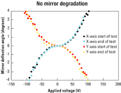
Unlimited mirror lifetime can be assured by ensuring all flexures do not exceed the yield stress for silicon. Properly designed single-crystal bulk micromachined silicon mirrors do not exhibit fatigue-related failures and therefore have a reliability advantage over surface micromachined mirrors. As an example, Figure 2 shows deflection data on a bulk micromachined mirror—before and after 106 million cycles. No degradation of the mirror is observed.MEMS mirrors may be driven by electrostatic, magneto-electric, thermal, or piezoelectric actuators. Piezoelectric and magneto-electric actuators are difficult to integrate in high densities. Further, magneto-electric and thermal actuators need to be well shielded to eliminate mirror crosstalk. Electrostatic actuation uses the least power and is best suited to massive integration, although issues with edge charge effects must be addressed.
Edge charge accumulates in the insulating dielectric layer around the edge of an electrode or actuator under the application of high voltages. These high voltages, typically 100-400 V, are necessary to drive the mirrors. As this charge accumulates, it causes the mirror position to shift in time for a constant applied voltage. Since the leakage currents are very small, the discharge time constant can be on the order of minutes to days, resulting in unreliable and unpredictable connections.The analyses are summarized in the Table. From a connection reliability standpoint, the obvious mirror technology choice is a bulk micromachined mirror with an electrostatic actuator. Undesired mirror movement, due to edge charge and other environmental effects, can be eliminated by a properly designed mirror control loop.
Connection reliability is compromised when the drive system that points pairs of mirrors to enable connections fails to tilt the mirrors accurately in the presence of environmental conditions and long-term drifts. The accuracy required to control insertion loss to within 0.05 dB (the repeatability as specified in Telcordia 1073) scales with port count and is on the order of 12 bits per mirror axis for a 1,000-port switch.
Mirror control approaches come in two configurations: open loop and closed loop. Component drift and environmental effects are handled quite differently by these two mirror control architectures.
In an open loop configuration, predetermined voltages are applied to the MEMS mirrors to tilt them to predetermined angles. An open loop mirror control configuration requires an accurate mapping of all component movements with respect to temperature. As the temperature changes, the MEMS mirror actuator voltages must be adjusted to maintain a reliable connection. Massive lookup tables or complex algorithms may be used to calculate updated actuator voltages based on temperature. These tables and algorithms must be periodically updated during connection calibration cycles, resulting in system downtime.
In a closed loop approach, the mirror tilt angle is continuously monitored and controlled using a sensor-based feedback system. The mirror-positioning accuracy is thus defined by the accuracy of the sensor, eliminating the majority of problems to which the open loop controller is sensitive, such as shock, vibrations, and drift due to the effects of edge charge and temperature changes.
Additionally, a well-designed closed loop controller may control mirrors past the snap-down point, a condition that occurs when the electrostatic drive force becomes larger than the restoring spring force. When snap-down occurs, the mirror actuator collapses onto the drive electrode.
Different types of position sensors can be used, from integrated mirror position sensors to sensing the infrared signal level in the output fiber. Each sensing method provides a different level of performance. Also, an outer, slower control loop may be used to monitor the optical performance of a few representative channels.
The performance of these channels is tracked, analyzed, and used to make adjustments for long-term higher-order alignment corrections to maintain optimum system alignment and minimize insertion loss. A properly tuned closed loop mirror controller affords the most reliable connections in the presence of shocks, vibrations, temperature changes, and long-term drifts.
Packaging reliability centers on the high-voltage connections to a large number of MEMS mirrors. Additional concerns involve the housing and mitigation of environmental effects. These latter concerns are addressed by temperature stabilizing, hermetically sealing, and damping the housing.
Large crossconnect switches can have more than 1,000 ports. With this number of elements, packaging the MEMS arrays, including the high-voltage wire bonds, is critical to maintaining reliable connections. There are two packaging options for the MEMS mirrors: The first involves a large number of high-voltage wire bonds, and the second is an integrated mirror controller chip.
More specifically, each MEMS mirror typically requires four electrical connections to drive the +X, -X, +Y, and -Y actuators. That means close to 4,000 high-voltage wire bonds are required between the mirror array and mirror-array package for a 1,000-port switch. It is practically impossible to fabricate a reliable package with this level of interconnections.
Therefore, electronic integration and interconnection management is very advantageous for a high-reliability system. That involves an integrated mirror structure using separate mirror-actuator, high-voltage, and CMOS layers. The high-voltage lines are connected to the mirror drive actuators within an IC environment. The CMOS layer is similarly interfaced to the high-voltage circuit. It provides the multiplexing and support logic necessary to interface with a high-level controller with a minimum of about 120 wire bonds. This type of packaging ensures a level of reliability commensurate with the OXC.Photo 2 shows the series of layers. The bottom layer is the high-level CMOS layer. The next level up is the electrode layer for driving the mirrors. The top level is the array of MEMS mirrors.
Connection reliability is a key requirement for MEMS-based OXC switches. By comparing and contrasting several engineering and design approaches, specific conclusions can be reached regarding the key OXC reliability drivers. Those conclusions include the superiority of single-crystal bulk micromachined mirrors, combined with a closed loop mirror controller.
Mirror arrays with integrated electronics have reliability advantages over passive mirror arrays with discrete electronics, principally due to a reduction in the number of high-voltage wire bonds. The optimum approach to vibration isolation is active damping of the MEMS mirrors by the mirror control loop.
Based on these conclusions, there are no fundamental reliability barriers preventing the launch of large-port-count MEMS-based OXCs into optical networks. MEMS-based all-optical switches easily exceed the reliability threshold.
Alex Harwit is co-founder and optical design director at Transparent Networks Inc. (Milpitas, CA). He can be reached via the company's Website, www.transparentnetworks.com.
- J.K. Lipton, A.D. Carbone, and P. Schwarzbach, "Industry Analysis Switching into Overdrive Intelligent Optical Switching: The Next Inflection Point in Optical Networking," J.P. Morgan Securities Inc., Equity Research, San Francisco, May 30, 2001.
- V. Poudyal, GR-1073-CORE, "Generic Requirements for Singlemode Fiber Optic Switches," Telcordia Technologies Inc., 2001.
- T.A. Shankoff, GR-63-CORE, "Network Equipment Building System (NEBS) Requirements: Physical Protection," Telcordia Technologies Inc., 1995.


