Single-channel amplification using semiconductor optical amplifiers
SOAs can provide a variety of benefits, either in tandem with EDFAs or as replacements.
BY IVAN ANDONOVIC, ROBERT PRESS, CRAIG MICHIE, and TONY KELLY, Kamelian Ltd.
The optical network has evolved considerably in recent years, with many new technologies employed or about to be employed to extend the reach and bandwidth of optical fiber further toward the edge of the network. Examples of recent developments include the emergence of optical add/drop multiplexers and crossconnects, tunable lasers, 40-Gbit/sec line rates, and systems designed specifically for regional, metropolitan, and access networks.The advantages of these new "building blocks" in terms of flexibility, transparency, and capacity are well known and documented. To gain these benefits, however, the network itself will become more complex and difficult to manage, as individual signals (or wavelengths) are switched and routed through the network in the optical domain. This network transparency and complexity has resulted in many new applications for low-cost, remotely or automatically controllable, single-channel amplification. This paper reviews some of those applications, and shows how they can be implemented in a cost- and space-efficient way using semiconductor optical amplifiers (SOAs).
Traditionally, in first-generation optical communications systems, the maximum transmission distance was simply limited by the signal power launched and fiber attenuation coupled with a known receiver sensitivity. These transmission systems would comprise many independent, but similar, optical fiber spans with optical-electronic interfaces between them. Hence, they were relatively easy to characterize, monitor, and manage.
The advent of erbium-doped fiber amplifiers (EDFAs), and later DWDM, enabled these systems to increase in distance and capacity, but they were still essentially straightforward point-to-point links. With the move toward all-optical networking enabled by the technologies mentioned earlier, a signal remains in the optical domain and can take many different routes through a complex network-from source to destination. That results, among other things, in the requirement for increased amplification flexibility within the network. There are three different areas where amplification is deployed:
- Boost a laser output to a higher level (power booster).
- Boost a signal along the transmission line to compensate for loss from attenuation or splitting (line amplifier).
- Amplify before the receiver to improve its sensitivity (preamplifier).
Although optical amplifiers have a positive effect on power budgets, they do contribute noise to what is essentially an analog transmission link. A further ramification of all-optical networking is that the multiplexed signals within the gain bandwidth of an optical-fiber amplifier become unequal. With optical cross connects, for example, flexible connectivity in the spatial and wavelength domains means that each wavelength may have traversed different paths before detection, hence arriving at the receiver with a range of optical powers. Thus, there is a real need to be able to perform operations such as gain equalization on a per-wavelength basis.
Because of their small size, low cost, and integration potential, SOAs have received growing attention recently as the most efficient and cost-effective means of performing this per-channel signal conditioning. Two cases, the SOA as a preamplifier and the SOA as a power booster, illustrate this point.Practical optical receivers introduce thermal noise into a communications link, resulting in a minimum receiver power, below which error-free detection of the incoming optical data signal is not possible. This minimum power is typically characterized by the receiver sensitivity, which defines the received light level for a particular bit-error rate (BER).
With the advance of systems supporting 10-Gbit/sec and 40-Gbit/sec data rates, the receiver sensitivities are much reduced, compromising the power budget for a particular optical-path connection. In these cases, the use of an optical amplifier with each receiver to boost the signal power enables error-free operation despite considerably reduced signal powers at the input to the optical amplifier.
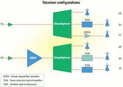
An arrangement such as that shown in Figure 1 can be used to increase the signal power or, with feedback, maintain the receiver input power at a preset level. That is relatively easily achieved by incorporating SOAs onto a receiver line card. Optical isolators and/or filters can be accommodated under certain circumstances to improve receiver sensitivity, but with additional cost and complexity.The SOA preamplifier described above will be integrated into a WDM receiver following the demultiplexer (see Figure 2). In this mode, the SOA provides the signal equalization function normally associated with the variable optical attenuator (VOA), while at the same time delivering gain into the system to optimize the receiver operation.
A detailed analysis of a communications link containing a range of EDFAs in tandem with SOAs requires careful consideration of the system dynamics and the temporal behavior of SOAs and EDFAs in particular. However, considerable insight into the relative performance of receiver topologies can be obtained using classical noise models to determine the contribution of each of the individual noise components. Here, the performance of a range of receiver configurations is considered for a 40-Gbit/sec transmission and illustrates the utility of SOAs within this role.
The BER is governed by the signal-to-noise ratio (SNR) at the detector,Referring to Figure 2, the signal photocurrent at the receiver due to the signal power is proportional to the incoming optical signal power and the gain (or loss) of the EDFA, demultiplexer, and VOA (or SOA) prior to the pin. In this model, no isolators or filters are assumed after the demultiplexer for the SOA and VOA cases. The noise term i-2noise includes all the contributing noise signals present within the receiver described above, for example:
- Noise sources from within the receiver (e.g., thermal noise and dark current).
- Signal shot noise.
- Shot noise from the spontaneous emission.
- Beat noise between the signal and spontaneous emission.
- Beat noise between the various spectral components of the spontaneous emission spectrum.
The merits of different receiver configurations can be evaluated by considering their respective BER performance versus input signal power. To illustrate the range of possible performances, six different receiver configurations have been compared (see Figure 2):
- The case where the receiving pin diode follows directly after the demultiplexer. That represents the baseline (back-to-back characterization) against which the improvements offered by other receiver configurations can be considered.
- The case where the sensitivity of the pin receiver is boosted using an SOA preamplifier immediately after the demultiplexer.
- The case where the sensitivity of the pin receiver is boosted using an EDFA preamplifier immediately after the demultiplexer.
- The case where an EDFA amplifier is used to boost the signal strength prior to the demultiplexer.
- The combination of an EDFA and a VOA to equalize for dynamic signal variations across the input spectrum.
- The combination of an EDFA to boost the incoming signal and an SOA to provide further signal amplification and compensation for dynamic variations.
For each of these cases, BER curves were generated according to the following parameters:
- EDFA: Gain = 25 dB, noise figure = 5.5 dB
- SOA: Gain = 20 dB, noise figure = 9 dB
- ID = 1 nA
- Responsivity = 0.7
- Receiver bandwidth = 40 GHz
- Average equivalent input NSD = 20 pA√Hz (representative of a good-quality receiver)
- Insertion loss of VOA = 1.5 dB
- Insertion loss of demultiplexer = 6 dB
- Demultiplexer channel bandwidth = 100 GHz
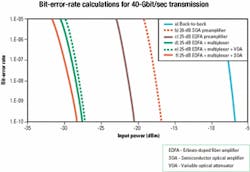
A comparative performance analysis for the cases considered above is shown in Figure 3.
The relatively low sensitivity of the back-to-back calculation reflects the fact that the dominant noise source at the receiver is thermal noise generated over a relatively wide bandwidth. Positioning an SOA preamplifier before the pin brings an immediate performance improvement of around 10 dB, producing a 40-Gbit/sec receiver with a sensitivity of -17 dBm. Within this context, the receiver operation is dominated by the spontaneous emission that the SOA delivers directly onto the receiver pin; consequently, significant further improvements are available by introducing a narrowband optical filter before the pin.Additionally, the SOA provides the capability for gain equalization, allowing the power on the photodiode to be regulated to a preset level. That enables the receiver performance to be optimized as well as protect sensitive re ceivers against surges in power.
For completeness sake, the performance curve is shown for the case where the SOA preamplifier is replaced with an EDFA. As expected, a reduction in necessary signal power broadly equal to the difference in noise figures is obtained. However, in practice, the difference between the SOA and EDFA will be smaller than that due to the fact the calculation does not account for the peak in the EDFA gain profile around 1,530 nm. The additional spontaneous emission associated with this peak will affect the overall receiver performance; hence, the difference between the SOA preamplifier and EDFA preamplifier will not be as significant as the graph suggests.
Positioning the EDFA in front of the demultiplexer improves the receiver performance by a further 10 dB, since the demultiplexer filters the spontaneous emission. The operation is now most strongly influenced by the beat between the signal and spontaneous emission (which only has a contribution within the signal bandwidth). A small portion of this benefit is eroded with the use of a VOA required for channel equalization.
Replacing the VOA in the above scenario with an SOA optimizes the receiver operation under the broadest range of circumstances, since the additional gain provided by the SOA causes the reception to be dominated by the signal's spontaneous beat noise. Where the input signal strength is too high, the SOA regulates the level at the pin to be within acceptable bounds. When the input signal is low, the SOA provides the additional boost required to optimize performance. Furthermore, the ease with which the SOA gain envelope can be modulated through the drive current ensures that this automatic power regulation facility is implemented within the required control bandwidths for the systems to operate effectively.
To sum up, clearly SOAs have an important role in high-data-rate communications links. Used on their own, they can improve the performance of a receiver by a significant amount; used in tandem with an EDFA, they ensure that the optimum receiver performance (that obtained when the receiver is dominated by the signal-spontaneous beat noise component) is achieved under all operating conditions. Moreover, the SOA provides the additional benefit of equalizing the signal presented at the receiver across the channel band and delivering signals optimized for a customer-specific receiver design.There is a growing move to use tunable-laser sources in network architectures for maximum flexibility and use of the wavelength resource. In general, the output power levels of tunable lasers, in relation to distributed-feedback sources, are modest and, given that an external modulator is required at data rates up to and beyond 10 Gbits/sec (which introduces additional insertion loss), it is desirable to boost the signal before transmission. In addition, the ability to pre-emphasize (power) each wavelength in a wavelength-division multiplexer to mitigate non-flat optical-amplifier gain profiles is much sought after.
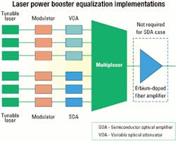
Candidate approaches to power boosting are highlighted in Figure 4. The initial designs are based on an EDFA solution with variable optical attenuators while the latter is based on an array of SOAs. The goal is to engineer a significant output power per channel with a power equalization capability of around 10 dB.
As the channel number increases, the EDFA gain is shared among the channels; the SOA solution is predicated on single-channel operation. In this latter case, the saturation output power of the SOA, less the multiplexer loss, sets the fundamental limit to the attainable power per channel while ensuring no detrimental levels of patterning result. The following illustrates the performance issues that must be considered.
Using VOAs to equalize the power across the transmission spectrum means that the signal is attenuated several times before it reaches the EDFA booster. The VOA itself has a minimum insertion loss of 1-2 dB and will further attenuate the signal by up to 10 dB to achieve the desired dynamic range of operation. Further losses of around 6 dB are in curred at the multiplexer.
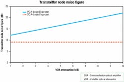
That has serious consequences for the overall noise figure of the transmission node (see Figure 5). Because the signal levels that are input to the EDFA power amplifier are severely attenuated (even in the case for low signal levels), the best noise figure that can be obtained is around 12-13 dB. The effect of increasing the VOA attenuation to achieve the required gain equalization exacerbates the problem and increases the noise figure to more than 20 dB.
In contrast, an SOA with a gain range of 15-25 dB and a maximum output power of 10 dBm provides the same functionality as above, eliminates the need for an EDFA, and has a noise figure fixed at that of the SOA. That's a significantly simpler solution with a much improved system performance. The only issue here is that the SOA and/or the system should be designed such that significant signal distortion (due to patterning) does not take place over this range.The semiconductor optical amplifier can be deployed in all-optical networking scenarios in two markedly different modes of operation: the linear and non-linear regimes. In the former case, it exhibits the characteristics of any linear amplifier, allowing its use in preamplifier, booster, and multichannel gating/ amplification applications.
However, in the non-linear regime, under dynamic gain saturation conditions, which can oscillate at speeds similar to that of the data being amplified, the SOA can be the basic building block for all-optical wavelength conversion and regeneration. Thus, one of the key operating issues, to ensure linear functionality, is the management of the input power levels so that the SOA is not driven into saturation, with the consequential detrimental effects of pattern-dependent waveform distortion (patterning) in single-channel and interchannel crosstalk in multiwavelength (WDM) cases.
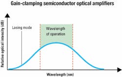
The most straightforward approach is to ensure a sufficiently low input signal power for a particular SOA design (gain and the output saturation power level). If that proves a significant overhead on the management of the all-optical implementations, especially on the monitoring complexity, then other SOA designs can be invoked based on the well-known technique of gain clamping. Gain clamping comes at the expense of a more complex device structure; a separate lasing mode is created outside the amplification bandwidth of the SOA (see Figure 6).
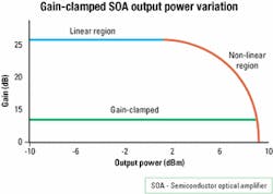
The external lasing mode effectively acts to reduce the gain available for the amplification process, thereby increasing the linear operating region (see Figure 7).
The lasing structure can be realized either in the longitudinal dimension (distributed Bragg reflector, distributed feedback, or external gratings such as fiber Bragg gratings) or indeed in the vertical dimension using a vertical-cavity surface-emitting laser. The longitudinal approach, used extensively in a number of pan-European research projects, is a straightforward addition to existing SOA technology and easily allows a range of gains to be implemented by design of the grating wavelength and strength. The gain is fixed at the laser threshold, ensuring linear operation of the optical amplifier over an extended range of input conditions.
But although that is effective, it must not be forgotten that the laser can be pushed below the threshold value at high input powers, inducing non-linear behavior. Gain-clamped SOAs provide a convenient means for "gating" small bands of wavelengths (typically around four), a capability that can be exploited within nodes performing wavelength-routing functions. However, gain-clamped SOAs provide a fixed gain that precludes the flexibility of power equalization provided by conventional SOAs, where the gain can be varied as long as linear operation is maintained.
The operation of SOA devices has been illustrated within two key network contexts; additionally, the concept of gating blocks of wavelengths (typically four) has also been briefly addressed. Clearly, the SOA has a significant role to play in all of these modes by providing a cost-effective solution that is physically small and has further integration potential through the use of emerging SOA array components. The performance benefits available from their use are clear and the associated costs that must be borne are minimal. In some cases, significant cost benefits may arise by eliminating the need for an EDFA or by allowing the specification of the EDFA to be relaxed.
Although not considered in detail here, the blocking properties of SOAs at low bias currents are also extremely useful, enabling channel routing functions such as reconfigurable add/drop multiplexers to be produced with off-channel isolation of better than 55 dB.
The SOA is a highly versatile component that can be deployed within a range of possible amplification and routing functions within the telecommunications network. The minimal space requirements, integration capability, and strong potential for cost reduction through scaled manufacturing processes will ensure that the SOA plays an increasingly important role in future network systems, both in tandem with and in place of other amplification technologies.
Ivan Andonovic is chief technology officer, Robert Press is vice president of marketing ([email protected]), Craig Michie is a senior systems engineer, and Tony Kelly is head of product development at Kamelian Ltd. (Glasgow, Scotland).


