Third-generation DWDM: extreme long-haul systems
Used successfully in undersea applications, extreme long-haul systems, due out later this year, face new challenges in terrestrial applications.
STEVE BAHRI and JON NAGEL, TerraWorx
The DWDM industry has undergone tremendous change since the early 1990s, when the initial applications were focused on relieving traffic congestion in backbone networks. The first generation of DWDM products, dubbed long-haul, offered a system reach of five to six spans. (Reach is the distance between optical-electrical-optical (OEO) regeneration, and span is the distance between two adjacent optical amplifiers.) The second generation of DWDM products, introduced in 1999 and known as ultra long-haul (ULH), extended the reach to 15 to 25 spans-the fiber-route distance from New York City to Chicago.
A third generation of DWDM products, the extreme long-haul (ELH), with a reach of 80 to 100 spans-the fiber route distance from New York City to Los Angeles-is likely to become available by year end. The technology has been successfully deployed over comparable distances in undersea systems for many years, but faces new hurdles on land.
The reach of ULH and ELH systems is limited by both distortion and noise. However, with higher signal powers, reduced spacing between channels, and longer transmission distances, distortion-induced limitations become more dominant. A good system design should balance the limiting effects of both distortion and noise in a way to minimize the overall transmission degradation.
The refractive index of the optical fiber varies slightly with wavelength. Since each optical pulse contains a small range of wavelengths, different parts of a pulse will propagate at different speeds. This difference results in broadening of the pulses, a phenomenon known as group velocity dispersion (GVD) or more commonly known as chromatic dispersion. When propagating over very long distances, each pulse broadens and overlaps with its neighboring pulses, eventually becoming indistinguishable at the receiver end.
Another potential source of pulse broadening is due to the fact the cross section of the core of the manufactured fiber is not perfectly circular. As such, the modes of commercial fiber are not orthogonally polarized, resulting in a fast axis and a slow axis. When the transmission pulse excites both axes, it becomes broader at the receiver end, since its two components propagate at different velocities, a phenomenon known as polarization-mode dispersion (PMD). For modern fiber, PMD-induced pulse broadening is relatively small compared to GVD effects for pulse rates of 10 Gbits/sec or lower over relatively short distances. However, PMD can become a limiting factor in ELH systems operating on older fiber designs or with pulse rates of 40 Gbits/sec and higher.
Nonlinear optical effects are a second source of pulse distortion. Although silica can intrinsically be considered a linear material, nonlinear effects become quite important when light is propagated in the small cross section of optical fiber over long distances. One class of such nonlinearities is stimulated light scattering. Rayleigh scattering is an example of elastic scattering for which the frequency of scattered light remains the same. By contrast, the frequency of scattered light is shifted downward in inelastic scattering such as Raman scattering and Brillouin scattering. Either of the inelastic scattering processes results in a loss of power at the incident frequency and constitutes a loss mechanism for optical fibers. These losses can be considerable, since the intensity of the scattered light in both cases grows exponentially once the incident power exceeds a threshold value.
A second class of nonlinear optical effects is due to the fact that the refractive index of silica varies nonlinearly as optical intensity increases. Since the optical intensity of a pulse varies at the leading and trailing edges, the frequency of the pulse can be shifted. This phenomenon is referred to as self-phase modulation and results in considerable spectral broadening of pulses propagating through the fiber. A similar problem arises when the intensity variations in one channel affect the phase of the other channels, resulting in cross-phase modulation. The most damaging nonlinear optical effect for DWDM transmission, however, is four-wave mixing, which can be viewed as a scattering process in which two photons of energies h1 and h2 create two new photons of energies h3 and h4. A significant amount of channel power may be transferred to neighboring channels, resulting in not only reduced power for a specific channel, but also leading to interchannel crosstalk that de grades system performance.
Of course, problems associated with pulse dispersion and optical nonlinearities are not unique to ELH applications; these issues are also present in both long-haul and ULH applications. However, what is unique to the ELH applications is finding a way to manage dispersion and nonlinearities accumulated over 80 to 100 spans.
Either reducing the optical power or increasing the diameter of the fiber can minimize most optical nonlinearities. Since in most terrestrial networks the fiber is already buried and deployed (i.e., no control over the diameter of fiber), the design of the terrestrial ELH products must focus on determining a sufficient optical power so that the pulses can propagate more than 80 to 100 spans without crossing the threshold where nonlinearities become prohibitively high.
In addition to distortion-related effects, noise is also a limiting factor in the ELH transmission systems. The dominant source of noise in an optical transmission system is the amplifier. Amplifier noise can degrade the system performance in two ways. First, the amplified spontaneous emission (ASE) noise will accumulate over the 80 to 100 amplifiers present in a typical ELH system. Second, increased ASE noise will saturate the optical amplifiers, resulting in reduced power level of signals. Subsequently, signal-to-noise ratio (SNR) at the receiver end could decrease to a point where detection becomes impossible.
Another source of noise in ELH systems is the reflection-induced noise. As the pulse travels through the fiber, some of its energy gets reflected back because of double Rayleigh scattering effects and refractive-index variations at splices and connectors, a phenomenon known as multipath interference (MPI). The MPI effects can become very stringent for systems using Raman amplification, especially if the quality of the splices and connectors at the fiber end is poor.
The fundamental difficulty in ELH transmission is balancing the effects of distortion and noise-two demons with a reciprocal relationship. The distortion-induced problems could be alleviated by lowering the optical power. But lowering the optical power will result in a lower SNR and ultimately erroneous detection of the signal at the receiver end. On the other hand, in creasing the optical power can minimize the noise-induced problems at the cost of increasing the distortion-induced problems.Ironically, these problems had been encountered and solved in undersea optical systems where transmission distances of 7,000-10,000 km are achieved without the use of OEO regeneration. The one major difference between an undersea system and a terrestrial system is the fiber plant. The undersea fiber cables utilize the best and latest fiber technology, and the amplifiers are spaced closely (typically 40-50 km) and uniformly such that the adverse effects of both nonlinear transmission and noise accumulation are minimized. Additionally, since the water temperature at the bottom of the ocean remains constant regardless of the temperature variations at its surface, temperature-related dispersion variations can be ignored in undersea networks.
So the good news is that almost all of the technology developed for and used in undersea systems can be used in terrestrial systems. However, additional solutions are necessary to overcome the widely varying parameters (fiber type, amplifier spacing, and fiber temperature) present in a terrestrial system.
Raman amplification is used in combination with erbium-doped fiber amplifiers (EDFAs) in almost all ULH solutions available on the market today, and it will most likely be required for ELH applications, as well. Raman amplification is a nonlinear process in which intense pump light couples to vibrational modes of the optical fiber and is then radiated at a longer wavelength, typically 60 to 100 nm longer than the pump frequency.As a result, Raman amplification turns the transmission fiber into a distributed gain medium. Since the gain spectrum is determined by the pump wavelength rather than the fixed energy level of a dopant, as is the case in the EDFAs, Raman gain can be created at any wavelength. As such, a wider gain spectrum can be obtained by using multiple pumps operating at different wavelengths, resulting in the transmission of more channels. Another advantage of Raman amplification is that the gain shape remains nearly constant regardless of the pump power, hence reducing the undesirable gain-spectrum-tilting affects that are associated with the EDFAs.
The critical issue with Raman amplification is determining the pump power necessary at the correct wavelengths to maximize the gain spectrum while minimizing nonlinearities. Raman amplification is not used in today's undersea systems because the amplifier spacing can be controlled while the cables are built and because it will require delivery of additional power to each amplifier.
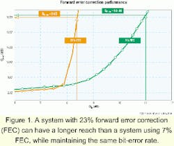
The use of forward error correction (FEC) techniques for fiber transmission was first pioneered in undersea transmission systems; it is only recently becoming a standard feature of ULH and ELH systems. Performance of a transmission system can be degraded in the presence of large amounts of uncorrected and undetected errors. FEC can be considered an "error control" mechanism, the underlying principle of which is to take user data (say, a 10-Gbit/sec channel), add some redundancy (say, 23% overhead), and transmit both the user data and redundant data for a line rate of 12.3 Gbits/sec. At the receiver end, the possibly corrupted signal is first processed, then errors are detected and corrected using the redundant data. Figure 1 illustrates a system's Q gain in decibels using various amounts of FEC overhead. Using 7% FEC overhead, the overall system Q can be improved from Qin=11 dB (measured at the receive end before correction is made) to Qout=16.5 dB after correction is made, a gain of 5.5 dB. However, by using a better coding mechanism and utilizing 23% FEC overhead, the system will maintain the same Qout=16.5 dB, while tolerating a higher count of errors (Qin as low as 8.5 dB). This means that a system using 23% FEC can have a longer reach than a system using 7% FEC, while maintaining the same bit-error rate (BER).
Although FEC technology has been around since the 1980s, finding a good code, a decoding algorithm, and efficient ways of implementing the decoding algorithms remain the principal challenges of developing a superior FEC solution. Nevertheless, ELH solutions can benefit from the established 23% FEC techniques used in undersea systems today. It is expected that the terrestrial ELH equipment manufacturers will continue to benefit from the pioneering work that the undersea system providers are conducting in this area.Chirped return-to-zero (CRZ) transmission is another undersea technique that is applicable to ELH systems. CRZ is a technique that shapes the pulse at the transmit end so that it becomes more tolerant of fiber nonlinearities as it travels over very long distances. There are other pulse-shaping techniques, such as quasi-soliton transmission, which would in principle provide the same benefit. Scholars have been debating the pros and cons of one technique over the other for many years without reaching a unanimous conclusion. A major advantage of the CRZ technique is that it is a proven and well-understood technology used in undersea systems for many years. It appears that the first terrestrial ELH products will also use the CRZ technique until other solutions are proved to be superior.
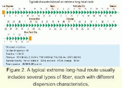
Dispersion management is another key consideration in ELH applications. The challenge is to maintain low dispersion at amplifier sites (local dispersion) and near-zero dispersion at the end nodes (global dispersion). This issue gets even more complex in a typical ELH route (i.e., New York City to Los Angeles), which usually includes several types of fiber, each with different dispersion characteristics.
Figure 2 shows such a route as well as some physical characteristics of the fiber plant. Notice that the global end-to-end dispersion can range from 20,000 psec/nm for lower pulses (1,535 nm) to 30,000 psec/nm for higher pulses (1,560 nm). To complicate the issue, the spacing between repeater sites, and therefore the amount of local dispersion compensation required at amplifiers, is not uniform. The local dispersion can be adjusted by deploying appropriate amounts of dispersion-compensating (DC) fiber at certain amplifier sites. The global dispersion can be controlled in a similar manner at the end-node terminals. But when deploying DC fiber, carefully consider a host of issues, such as the higher loss of DC fiber compared with regular transmission fiber, the input power limitations, the maximum length of DC fiber that can be spooled and housed at each node, and the uniformity of dispersion correction among different pulses.
PMD is another source of pulse dispersion that must be managed properly. Although PMD is not a limiting factor when transmitting 10-Gbit/sec channels on modern optical fiber, it severely limits the performance of a DWDM system for transmission of 40-Gbit/sec channels or when using fiber with PMD of 0.1 psec/ or higher, such as the fiber manufactured before 1985. Since the PMD effects increase with the square root of the length of the system, it can also become a limiting factor for ELH applications even when the signal rate is kept at 10 Gbits/sec and transmitted over modern fiber. One technique used to correct the PMD effects, known as the principal state launch, is to make sure that the pulse is injected in only one of the two axes-either the fast axis or the slow axis of the fiber. In this case, no adjustment is needed at the receive end. The other technique is to adjust for the PMD at the receive end at the first-order or higher-order levels.Gain spectrum equalization refers to a broad range of techniques used to maintain the spectrum of the gain as flat and uniform as possible under varying levels of optical intensity, whether it is obtained from EDFAs or Raman amplifiers. A widely used technique is to adjust the gain shape by utilizing gain-flattening filters at each amplifier site or as often as needed. However, a better technique is to flatten the gain spectrum dynamically, by using a feedback mechanism, based on the optical intensity of each individual channel. Improved amplifier designs with increased gain spectrum stability are another way for maintaining a flat-gain shape under various optical power levels.
New fiber design with very small variations in the dispersion characteristics over the entire band of wavelengths will reduce the nonlinear effects. Although the improvements in the fiber-making techniques have been remarkable in the last decade, many fiber manufacturers are striving toward producing higher-purity optical fiber with reduced dispersion slope.
Mathematical modeling and system simulation techniques that can accurately model ELH transmission are indispensable tools for a successful design. Since building a 100-repeater network for testing purposes is prohibitively expensive, mathematical modeling of such systems is necessary to predict system performance. Similar techniques used and validated for modeling undersea systems with EDFAs are now becoming the framework upon which new simulators are developed.
These new simulators can take into account Raman interaction between amplifiers, signals, and noise as well as noise generation and its dependence on temperature. Multipath interference caused by double Rayleigh scattering also needs to be computed and added to the receiver degradations. Computationally effective algorithms must be employed to enable fast calculation of Raman gain and noise in terrestrial spans with different length and fiber composition. It is crucial to test the accuracy of these modeling techniques by validating the simulated result against results obtained from recirculating loop experiments.
The principal purpose behind all of the techniques and technology used to overcome ELH system challenges is to create, for any given system, the highest Q margin possible. This margin can then be used to build the truly transparent networks of the future. How and where the Q margins are allocated will determine the extent and nature of such transparent networks. For example, it's possible to build a 64-channel point-to-point DWDM system between New York City and Los Angeles by allocating all of the available Q margins to distance and capacity. Or the margins can be allocated for building mesh optical networks with multiple optical crossconnect switching nodes, where each route is designed for the worst case distortion and noise scenarios. The first applications of the ELH systems are likely to be the point-to-point DWDM systems, followed shortly by routes on the mesh optical networks.
Study after study has proven that packet-based data transmission will dominate the traffic carried over the backbone networks. These same studies have concluded that the distribution pattern of the packet-based data traffic is very different from the switched-based voice traffic for which existing backbone networks were designed and built.
This situation is similar to the traffic changes that took place in the airline industry in the last five decades. When air transport was coming of age in the early 1950s, airline companies were operating in a large number of airports across the United States, because the majority of passengers were people conducting regional business. As such, transcontinental flights were a collection of short hops from airport to airport.
Another reason for this multihop operation was that technology was not yet advanced enough to allow for non-stop transcontinental flights. As the nature of businesses changed from regional to national and then international, and as jet engine technology made the long-distance air transport possible, the major airline companies reconsidered their operation and evolved to a hubbed structure, with each company focusing in a specific geographical market. Regional flights were still available through shuttle services offered by the major airlines or by independent operators for routes outside the markets served by the major airlines.
A similar evolution will take place in the telecommunications industry for two reasons. First, packet-based data traffic is no longer regional. Data traffic tends to travel nationally and internationally, whereas voice traffic is typically concentrated within a small community of interest and travels regionally. Second, ELH DWDM technology combined with large-scale routers, sporting 10-Gbit/sec interfaces and multiterabit switch capacity, will enable a hubbed network operating above the existing backbone networks.
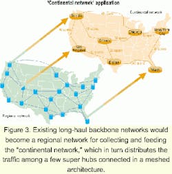
The existing backbone networks were built, and built very well, to behave as a collecting network and as such are not suitable for evolving into a distributing net work. Rather, the distributing network, called the continental network, must be built and operated as a separate and independent network, interfacing with the regional network at super hubs.
Figure 3 illustrates how existing long-haul backbone networks will evolve into a regional network for collecting and feeding the continental network, which in turn distributes the traffic among a few super hubs connected in a meshed architecture.
For carriers, the key operational benefits of a continental network are three-fold. First, instant provisioning of 10-Gbit/sec wavelengths independent of the distance between super hubs, a process that today takes two to four weeks. Second, the reduced operating cost of the network realized by removing maintenance-intensive OEO regeneration nodes. Third, the increased reliability of the network realized by simplifying the architecture.
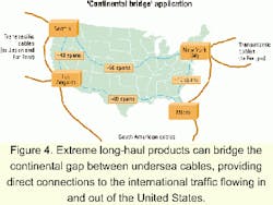
Another application for ELH systems is to connect the undersea cables in a direct point-to-point architecture. There are four major undersea cable landings in the United States today. European traffic is terminated in New York City. South American traffic is terminated in Miami and Los Angeles. Far east traffic is terminated in Seattle and Los Angeles. As Figure 4 indicates, the ELH systems can bridge the continental gap between these four landings and provide direct connectivity between the international traffic flowing in and out of the United States. Especially desirable is establishing an economical link between the Far East and European traffic by connecting the Pacific and Atlantic undersea cables. Of course, another way of achieving the same goal is to build a trans-Siberian network-another application for ELH systems.
Transmission networks will evolve toward transparency. As this evolution occurs, certain engineering rules will become more stringent. Optical paths will be engineered to support the worst-case scenario without knowing from the onset where that path is or what its characteristics are. Network reach will continue to increase as optical crossconnects provide multiple optical paths between super hubs. Similarly, path engineering problems will have to be solved for the whole network, instead of network segments.
As the engineering of these networks be comes more difficult, extracting the overall system Q is even more important. Expertise in managing those hard-earned Q margins-how much to allocate for deterministic parameters (fiber loss) and how much to allocate for stochastic parameters (end-of-life)-is critical.
ELH systems are engineered to achieve the same two objectives, generating the highest Q per a given system and to efficiently manage Q margin allocations. For that reason, among others, ELH solutions will serve as an enabling technology to evolve transport networks toward transparency.
Steve Bahri is director, application engineering, and Jon Nagel is chief technology officer at TerraWorx (Shrewsbury, NJ).


