10GBase-LX4 vs. 10GBase-LRM: A debate
Editor’s Note: With 10GBase-LRM nearing ratification, systems suppliers will soon face the choice of which transceiver type to incorporate in their designs-and network designers will need to determine which transceiver to specify in their purchases. To help with these decisions, Lightwave has invited articles from both camps to make the case for their offerings.-Lightwave editorial staff
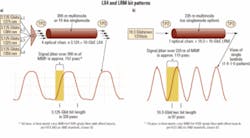
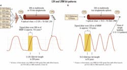
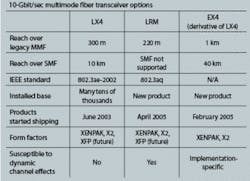
LX4 or LRM: An implementer’s dilemmaBy Bryan Gregory, John Dallesasse, and Bor-long Twu As 10-Gigabit Ethernet broadly rolls out and increasing numbers of enterprises begin the process of evaluating network upgrades, users are confronted with a large and complex array of physical-layer interfaces that require consideration. The process is not as simple or foolproof as it should be. Considering the technical challenges, though, the process also demonstrates tremendous accomplishments from a diverse collection of vendors. From a historical perspective, “Ethernet” is thought of as ubiquitous, cost-effective, and robust. Pushing this mature standard from 10 Mbits/sec to the current 10 Gbits/sec has been a tremendous feat. The new 10-Gbit ports are a thousand times faster than the originals. These new interfaces often run over cabling installed years ago and intended for much slower signals.Numerous physical-layer interconnects are available to address 10-Gbit/sec data transmission. These include 10GBase-LX4, CX4, SR, LR, and ER, as well as emerging 10GBase-T (802.3an), 10GBase-KX4 (802.3ap), and 10GBase-LRM (802.3aq). With all of these options, it can be a difficult process to sort through the requirements of a specific implementation. In this article, we will briefly discuss some of the issues surrounding the two options that meet existing installed multimode-fiber cabling plant in building backbone, switch-to-switch, data center, and other enterprise-related environments. The two options are the mature IEEE 802.3ae-2002 LX4 standard and the draft LRM standard, which is currently in IEEE-SA Sponsor Ballot.10GBase-LX4 is a mature port type that has been in use for several years. Many tens of thousands of LX4 modules have been shipped. LX4 is robust, stable, and has been observed with real links to have substantial performance margin. Multiple LX4 module vendors are currently shipping production units. An industry trade group, the LX4-TG (LX4 Trade Group), has been formed to promote LX4 technology.The LRM standard is currently being developed within the same IEEE group that generated the LX4 standard. The specifications are being developed to cover 220 m, a subset of the existing installed multimode-fiber cabling plant. Within the 802.3 group, the stretch goal of 300-m coverage was abandoned after many months of hard work; achieving a robust 300-m version of LRM was deemed too risky and limited the group’s ability to release the standard in a timely manner. Indeed, several participants representing network equipment vendors reluctantly agreed to this significant concession. This reduced-distance compromise will enable more robust LRM operation, but may limit the product’s usefulness in some building backbone applications. The LRM standard’s completion date is now projected to be mid-2006, instead of the previous early 2006 target.The slower (3.125 Gbits/sec) signal of the LX4 (a) can more easily handle the 157 psec of differential mode delay encountered over 300 m of older 62.5-µm multimode fiber than the LRM signal (b). LRM devices therefore require electronic dispersion compensation, adding to their cost. A brief performance summary of the LX4 standard, the LRM standard, and a derivative of the LX4, called the EX4, is listed in the table below.
The same LX4 module can be used for both existing installed 300-m spans of multimode fiber and 10-km spans of singlemode fiber. Other technologies such as the EX4 can extend multimode reach well beyond 300 m. LX4 represents a mature platform that is fully deployed in the field today using proven technology. The versatile modules provide the user with the flexibility of use in either multimode or singlemode fiber networks and, thus, reduce inventory because fewer module types need to be held in reserve.One of the advantages claimed for LRM is cost to the end user. However, the cost analysis of the basic LRM module relative to LX4 is not as simple as LRM supporters suggest.LX4 technology does use multiple lasers, but they are lower-speed devices produced with simpler processes. This creates a design with more parts, but enables the use of substantially less expensive components. Operation at 3.125 Gbits/sec per channel enables vendors to piggyback on the mature OC-48 laser market as well as the commodity Fibre Channel market. Over the last few years, multiple component vendors have also successfully developed low-cost optical multiplexers and demultiplexers.LRM modules use a single higher-speed laser operating at 10.3 Gbits/sec rather than 3.125 Gbits/sec. This creates a simpler optical path, but requires more expensive components. The LRM laser can either be a distributed-feedback (DFB) laser, a vertical-cavity surface-emitting laser (VCSEL), or a Fabry-Perot (FP) laser. Both DFBs and VCSELs provide a very clean, single-wavelength output, which minimizes signal degradation due to spectral effects. On the other hand, an FP laser source produces a range of different wavelengths. Each of these wavelengths travels through the fiber at slightly different speeds, creating additional jitter that must be recovered by the EDC circuit at the receiver. While small, this added jitter could compromise operation on some fibers.The EDC chips used in the LRM modules are also very complex and require a highly linear transimpedance amplifier (TIA) and a high-speed photodiode with a large surface area capable of capturing all of the optical modes at the output of a fiber. Thus, LRM offers the advantage of fewer components, yet the increased performance requirements for each individual element may be a substantial barrier to the overall module cost savings speculated by LRM advocates.The IEEE 802.3aq group has made significant progress on a wide array of problems that the LRM has faced, but several key issues remain. One fundamental issue that is not likely to be addressed in a substantive way by the standard is the time-varying nature of the multimode fiber’s impulse response. While the IEEE 802.3aq group has done an outstanding job in modeling and understanding the static characteristics of the link, work on dynamic effects has been substantially more limited.Relatively minor thermal or mechanical interactions with a fiber can result in significant modal changes. Changes in temperature (thermal perturbations) can be caused by running a fiber near an outside wall, an air-conditioning unit, or a heat source such as an Ethernet switch or server. Discrete mechanical perturbations include optical connectors or points of pressure applied to the fiber. Distributed mechanical perturbations can come from bends or stresses that pull, push, or twist a fiber over some length. Time-varying mechanical changes can occur from fan vibrations or other oscillating mechanical sources.As can be seen from the two bit-pattern diagrams in the figure, multimode fiber creates significant signal jitter. Older fibers were often designed to accommodate 10- or 100-Mbit/sec signals. Upgrading them to 10 Gbits/sec is like increasing the interstate highway speeds from 65 mph to 6,500 mph, without resurfacing or widening the lanes! With an offset launch, approximately 157 psec of differential mode delay are generated over 300 m of multimode fiber (or approximately 115 psec for 220 m). When this is applied to a slower LX4 signal with a bit period of 320 psec, the net effect is manageable. However, when this jitter is applied to a 97-psec LRM signal, the jitter completely overwhelms the data.Advanced EDC techniques can compensate for this jitter and enable the signal to be extracted, assuming the jitter is not too large and the transfer function of the fiber does not change too rapidly. Over time, it is likely that this can be done in a fairly robust manner, but further advances may be required to accomplish this with low-power-dissipation ICs that can rapidly adapt to dynamic channels.For some fibers, the time-varying nature of the optical channel may cause links to function initially, but to go through periods of time where link health is randomly impaired, either through a complete inability to transmit data or through the appearance of dribbling bit errors. Because the current draft of the 10GBase-LRM standard neither specifies a required optical module adaptation rate to changes in the fiber impulse response nor provides a standard method for testing the EDC adaptation time, the likelihood of dribbling errors will depend upon proprietary implementation details of the LRM optical module and EDC IC. System vendors developing qualification procedures will be under tremendous pressure to fully address all of the dynamic worst-case testing requirements and interoperability issues. This will be important because larger enterprise and campus end-customers will be understandably agitated if their network backbone randomly collapses or degrades during operation!Even the static characteristics of links within the 220-m range of the LRM standard may pose a problem. The percentage of installed fiber links with characteristics that EDC ICs will be unable to stably adapt to is not known; very limited data on the distribution of PIE-D values (a metric used to assess the ability of an EDC IC to equalize a link) in the installed base is available, making the assessment of network failure risk almost impossible. Certification of fiber plants for operation with LRM transceivers will also be a significant challenge given the high levels of difficulty in measuring PIE-D in the field.Another key problem with LRM deployment is the requirement of a dual launch to improve the probability of establishing a link. Offset launch is a proven method from prior Ethernet standards of ensuring stable operation because it restricts the number of modes excited in the fiber and thereby minimizes the amount of differential mode delay. Unfortunately, the probability of link operation for LRM in the installed base would have been unacceptably low if only offset launch were specified. Rather than accept a low coverage percentile, the IEEE 802.3aq group decided to add the option of a center launch. This creates risk, because the dynamic behavior of the fiber modes is much less stable in the case of a center launch. Minor perturbations of the fiber or interconnect points can cause more substantial changes in the fiber’s impulse response when a center launch is used. Overall link stability is thus critically dependent upon the adaptation time of the EDC IC.Installers will also need to try various combinations of offset and center launch cases on both ends of the link in situations where challenging fiber is encountered. Both network installation and troubleshooting will therefore be more complex with LRM links. Overall, the unknown probability of network instability and dependence of stability on parameters deemed outside the scope of the LRM standard are among the greatest disadvantages of what is otherwise a very interesting technology.Newer is not always better. After several years of volume manufacturing, product improvements, process optimizations, manufacturing transfers, subcomponent cost reductions, and the familiarity of propagating 10 Gbits down an existing installed imperfect channel, the LX4 suppliers have an extensive menu of both technical and economic responses to additional market entrants seeking to address the multimode 10-Gigabit Ethernet space.As this process plays out in the open market, it will be interesting to watch the ebb and flow of the technical and business landscape. As with all Ethernet products, LX4 with its entrenched field population, superior reach on multimode fiber, evolutionary upgrade path, flexibility for use in singlemode fiber applications, and multiple vendor support may survive as the fittest. In the long run, as the LX4 vendors gain increasing experience in field implementations using imperfect channels (installed multimode fibers) to propagate 10 Gbits, they are well positioned to expand into other technologies such as LRM if necessary. Vendors with both LX4 and LRM capabilities may serve customers the best and ultimately win the greatest share of the market.Bryan Gregoryis president of BEA Inc. (Pittsburg, PA; www.beainc.com). He was previously vice president of marketing at EMCORE Corp., where he worked on this article. John Dallesasseis director, development, at EMCORE Corp. (Somerset, NJ; www.emcore.com). Bor-long Twuis CTO of BeamExpress Inc. (Sunnyvale, CA; www.beamexpress.com).LRM is ready for marketBy Scott Schube and John Kikidis While 10GBase-LX4 is the first optical interface standard developed to run at 10 Gbits/sec (10G) over multimode optical fiber backbones in vertical risers, 10G optical transceivers based on the newer 10GBase-LRM IEEE standard are expected to establish themselves as the preferred option for both current and future smaller form-factor modules because of the LRM’s lower cost, smaller size, and greater manufacturability. LRM-compliant optical transceivers are now deploying to system vendor customers, and the standard itself is nearing final approval. Widespread production of LRM optical transceivers is expected to happen this year and will be a key enabler for 10G in the enterprise networking space.
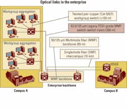
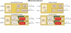
Figure 1. Multimode fiber is the predominant fiber type in today's enterprise network. As data rate requirements reach 10G, new transceiver technologies must be deployed. This article will review the multimode backbone application for which LRM was designed and describe the basic LRM architecture, including the fundamentals of the electronic dispersion compensation (EDC) technology that is a key element of this approach. It will address the expected transmission performance of LRM devices and will compare LRM against the incumbent multimode 10G approach, LX4, to outline the multiple advantages of the LRM in size, cost, and manufacturability. Finally, the article will discuss the status of the IEEE standard and vendor support for LRM components and modules.Multimode fiber dominates the installed base of fiber plant for data communications (see Figure 1). Older multimode fibers installed in the early 1990s exhibit large amounts of modal dispersion, making for a challenging transmission channel, particularly at 10G data rates. For instance, 10G 850-nm devices for multimode fiber (10GBase-SR) are guaranteed to operate up to only 26 m on worst-case 62.5-µm multimode fiber. For vertical-riser applications in building backbones, transmission distances of up to 300 m are required, and pulling new fiber is not a cost-effective option. The requirements of the vertical-riser application must be addressed to make 10G optical deployment a viable alternative in the enterprise backbone.The current standards-based design for the vertical-riser link is known as 10GBase-LX4. LX4 uses a CWDM approach using four wavelength-specific transmitters near 1300 nm, a CWDM multiplexer and demultiplexer, and four receivers (see Figure 2). The advantage of this approach is that the transmitters and receivers are all operating at about one-quarter of the data rate; hence, the data transmission is robust to modal dispersion (specified in the IEEE standard up to 300 m). The disadvantages of this architecture are significant challenges in cost, size reduction, and manufacturability.As a result of these disadvantages, vendors have developed an alternative approach called 10GBase-LRM, which is currently being standardized by the IEEE. LRM uses a 10G serial approach with a single 1310-nm transmitter and a receiver with an adaptive electronic equalizer IC in the receive chain (Figure 2). This adaptive equalization technology, known as EDC, is used to compensate for the differential modal dispersion (DMD) present in legacy fiber channels.The LRM architecture is in many ways similar to the architecture of other serial 10G PMDs (SR for short reach, LR for 10-km reach, etc.), with a few key differences.
Figure 2. As the XENPAK/X2 and XFP illustrations show, LRM architectures are less complex than LX4 approaches. First, an LRM optical transmitter must transmit at 1310 nm over multimode fiber. This yields longer transmission distances because the original installed multimode fibers were optimized for operation at 1300 nm to work with LED sources, before the mass commercialization of lasers for communication applications. The LRM application allows the use of Fabry-Perot lasers, which will be less expensive than the distributed feedback (DFB) lasers typically used for telecom applications because of the ability to operate without an optical isolator.Second, an LRM optical receiver must accommodate a multimode input but have high responsivity at 1310 nm. The receiver must also have a linear output to preserve the incoming waveform shape; this is key to being able to equalize the waveform further down the receive chain.Third, an LRM transceiver incorporates electronic dispersion compensation in the receive chain to equalize the modal dispersion introduced by a long length of multimode fiber.As stated previously, EDC forms an essential element of LRM designs. EDC technology is based on the same principles of channel equalization that have been used successfully in nearly every type of communication channel at lower data rates (e.g., disk drives, mobile telephones, and wired communication channels). The challenges to using this technology in the LRM application are the very high speeds involved and the constraint that LRM must be completely backward-compatible with existing 10G protocols. This last constraint rules out training sequences and other techniques that help the equalizer adjust in other applications, and instead mandates an equalizer that can blindly adapt to the channel.
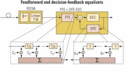
Figure 3. EDC is an important component of LRM designs. A combination of feedforward and decision-feedback equalizers will likely represent the most common approach. There are a number of architectures one can use to achieve the channel equalization, with two approaches being primarily pursued for EDC applications:• A combination of a feedforward and decision-feedback equalizer (FFE+DFE; see Figure 3), accompanied by a control loop algorithm to intelligently optimize the filter tap coefficients for the equalizers.• A maximum-likelihood sequence estimator (MLSE) that uses a Viterbi-like digital signal processing technique to determine the most likely bit-sequence to have been transmitted using a decision tree and error estimation (metrics) on the received data signal.In the FFE setup, a finite-impulse-response (FIR) filter is added after the optical-to-electrical conversion. A versatile implementation is typically based on a tapped delay line structure. This filter has several stages, each consisting of a delay element, a multiplier, and an adder. After every delay element, an image of the nondelayed input is multiplied with a coefficient and added to the signal. The number of filter stages used and the coefficients chosen are crucial for effective dispersion cancellation. Automatic and adaptive control of the filter coefficients is also essential.The second stage is usually the DFE. This structure is an FFE with a second FIR filter added to form a feedback loop. Again, the coefficients of both filters require active control. Today’s IC technology permits FFE-only or combined FFE/DFE structures that operate at 10G bit rates to be built as either a standalone chip or integrated with a clock-data recovery or demultiplexer chip with an extra power consumption of about 500 to mW.An MLSE approach uses a digital signal processor to perform complex mathematics on the incoming data stream to reconstruct the transmitted signal. While this equalization approach promises high performance, it needs the signal to be in digital form at the input, which requires an analog-to-digital (A/D) converter sampling (at least) with the speed of the line rate and with a high resolution (typically 4 to 6 bits/sample). Given their additional complexity, current MLSE devices exhibit power dissipation of about 3 to 4 W, which makes them inappropriate for the small-form-factor modules that are typically used in multimode-fiber enterprise applications.LRM is currently specified in the IEEE standard to a distance of 220 m, which represents the 99% coverage level (per the standard, LRM is guaranteed to cover 99% of installed fibers to 220 m). Beyond this distance, simulations performed in the standards task force indicate that the LRM standard is expected to cover nearly all (> 90%) installed fibers to 300 m (see, for example, http://www.ieee802.org/3/aq/public/sep05/ewen_1_0905.pdf). Combining this coverage number with the actual lengths of installed multimode fibers in the field (see http://www.ieee802.org/3/10GMMFSG/public/mar04/flatman_1_0304.pdf) gives LRM an overall expected coverage of the installed multimode fiber base exceeding 95%. Interoperation among various LRM devices has been demonstrated over 600 m of nominal 62.5-µm multimode fiber (see http://www.ieee802.org/3/aq/public/oct05/rausch_1_1005.pdf). As LRM optical transceivers get into the field in the next few months, these numbers can be correlated with more empirical data on installed fibers.The LRM approach has three key advantages over LX4.The first is size. LX4 uses four lasers and laser drivers and four photodiodes and preamplifiers, which makes size reduction an enormous challenge. LRM, by contrast, adds little to no additional size, as the architecture can use the same optical component footprint as existing 10G modules, with the EDC functionality integrated into the existing CDR/SerDes chipset.The most tangible benefit of this is that LRM is expected to have no difficulty fitting into the smaller XFP form factor that is expected to dominate 10G module shipments within the next few years. In contrast, there is no clear pathway for LX4 to fit into an XFP package. In addition to the potentially insurmountable barrier of fitting four optical transmitters and receivers, a CWDM multiplexer/demultiplexer pair, and the associated packaging into an XFP form factor, an LX4 implementation in XFP would also need a XAUI gasket chip to demultiplex the incoming electrical signal by four, pushing power dissipation well beyond the acceptable envelope for XFP modules.LRM devices are also expected to cost less than their LX4 counterparts. As a result of manufacturing yields and significant packaging and assembly cost, LX4 pricing is currently above that of 10-km LR transceivers. In contrast, LRM substitutes low-cost silicon for the optical complexity of LX4, and so is able to achieve substantially lower costs. LRM pricing is expected to be between that of 850-nm SR and 10-km LR parts, with an ability to follow other 10G PMDs down the cost curve over time. In contrast, in addition to the current significant price premium for LX4 vs. LRM, LX4 is expected to have difficulty reducing costs over time.Finally, current LX4 approaches require a significant amount of assembly (splicing, fiber attach and routing, and in some cases multiple PC boards, flex cables, etc.), which naturally reduces yields at the module level and makes the module difficult to manufacture. Again, the photo effectively illustrates the problem. LRM, in contrast, requires no extra assembly compared with existing SR and LR 1-Gbit/sec and 10G parts.The IEEE has established a task force to work on the 10GBase-LRM standard, and significant simulation and empirical work has been done over the past year and a half to define the multimode-fiber channel and the technical parameters required to interoperate over that channel. As of this writing, no major technical changes were expected to the draft standard, which is on track for final approval by July.Four optical transceiver vendors recently performed interoperability testing over a number of difficult multimode-fiber channels to demonstrate the viability of the standard, with excellent results (see http://www.ieee802.org/3/aq/public/oct05/rausch_1_1005.pdf for details).The vendor community is strongly backing the LRM standard. Several optical transceiver vendors are sampling product already, and more than 10 silicon vendors are developing ICs with EDC functionality for the LRM application. In addition, several leading optical component suppliers have introduced LRM optical transmitters (TOSAs) and receivers (ROSAs). Multiple system vendors are expected to announce support for LRM over the course of the next few months.While LX4 is the first standard developed to run at 10G over multimode-fiber backbones in vertical risers, LRM is expected to establish itself as the long-term preferred approach for both current and future smaller-form-factor modules due to its lower cost, smaller size, and greater manufacturability. The LRM approach is supported by the majority of the vendor community, and the IEEE standard and the key technological building blocks for LRM are all falling into place to enable LRM production this year.Scott Schube is strategic marketing manager, Intel Optical Platform Division (Newark, CA; www.intel.com). John Kikidis is strategic marketing manager, Intel Optical
