Editor’s Note: With 10GBase-LRM nearing ratification, systems suppliers will soon face the choice of which transceiver type to incorporate in their designs-and network designers will need to determine which transceiver to specify in their purchases. To help with these decisions, Lightwave has invited articles from both camps to make the case for their offerings.-Lightwave editorial staff
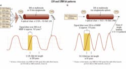
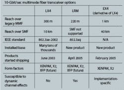
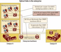
LX4 or LRM: An implementer’s dilemmaBy Bryan Gregory, John Dallesasse, and Bor-long Twu As 10-Gigabit Ethernet broadly rolls out and increasing numbers of enterprises begin the process of evaluating network upgrades, users are confronted with a large and complex array of physical-layer interfaces that require consideration. The process is not as simple or foolproof as it should be. Considering the technical challenges, though, the process also demonstrates tremendous accomplishments from a diverse collection of vendors. From a historical perspective, “Ethernet” is thought of as ubiquitous, cost-effective, and robust. Pushing this mature standard from 10 Mbits/sec to the current 10 Gbits/sec has been a tremendous feat. The new 10-Gbit ports are a thousand times faster than the originals. These new interfaces often run over cabling installed years ago and intended for much slower signals.Numerous physical-layer interconnects are available to address 10-Gbit/sec data transmission. These include 10GBase-LX4, CX4, SR, LR, and ER, as well as emerging 10GBase-T (802.3an), 10GBase-KX4 (802.3ap), and 10GBase-LRM (802.3aq). With all of these options, it can be a difficult process to sort through the requirements of a specific implementation. In this article, we will briefly discuss some of the issues surrounding the two options that meet existing installed multimode-fiber cabling plant in building backbone, switch-to-switch, data center, and other enterprise-related environments. The two options are the mature IEEE 802.3ae-2002 LX4 standard and the draft LRM standard, which is currently in IEEE-SA Sponsor Ballot.10GBase-LX4 is a mature port type that has been in use for several years. Many tens of thousands of LX4 modules have been shipped. LX4 is robust, stable, and has been observed with real links to have substantial performance margin. Multiple LX4 module vendors are currently shipping production units. An industry trade group, the LX4-TG (LX4 Trade Group), has been formed to promote LX4 technology.The LRM standard is currently being developed within the same IEEE group that generated the LX4 standard. The specifications are being developed to cover 220 m, a subset of the existing installed multimode-fiber cabling plant. Within the 802.3 group, the stretch goal of 300-m coverage was abandoned after many months of hard work; achieving a robust 300-m version of LRM was deemed too risky and limited the group’s ability to release the standard in a timely manner. Indeed, several participants representing network equipment vendors reluctantly agreed to this significant concession. This reduced-distance compromise will enable more robust LRM operation, but may limit the product’s usefulness in some building backbone applications. The LRM standard’s completion date is now projected to be mid-2006, instead of the previous early 2006 target.The slower (3.125 Gbits/sec) signal of the LX4 (a) can more easily handle the 157 psec of differential mode delay encountered over 300 m of older 62.5-µm multimode fiber than the LRM signal (b). LRM devices therefore require electronic dispersion compensation, adding to their cost. A brief performance summary of the LX4 standard, the LRM standard, and a derivative of the LX4, called the EX4, is listed in the table below.
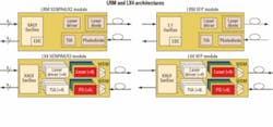
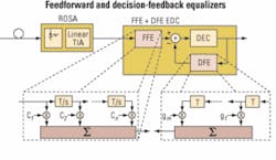
Figure 3. EDC is an important component of LRM designs. A combination of feedforward and decision-feedback equalizers will likely represent the most common approach. There are a number of architectures one can use to achieve the channel equalization, with two approaches being primarily pursued for EDC applications:• A combination of a feedforward and decision-feedback equalizer (FFE+DFE; see Figure 3), accompanied by a control loop algorithm to intelligently optimize the filter tap coefficients for the equalizers.• A maximum-likelihood sequence estimator (MLSE) that uses a Viterbi-like digital signal processing technique to determine the most likely bit-sequence to have been transmitted using a decision tree and error estimation (metrics) on the received data signal.In the FFE setup, a finite-impulse-response (FIR) filter is added after the optical-to-electrical conversion. A versatile implementation is typically based on a tapped delay line structure. This filter has several stages, each consisting of a delay element, a multiplier, and an adder. After every delay element, an image of the nondelayed input is multiplied with a coefficient and added to the signal. The number of filter stages used and the coefficients chosen are crucial for effective dispersion cancellation. Automatic and adaptive control of the filter coefficients is also essential.The second stage is usually the DFE. This structure is an FFE with a second FIR filter added to form a feedback loop. Again, the coefficients of both filters require active control. Today’s IC technology permits FFE-only or combined FFE/DFE structures that operate at 10G bit rates to be built as either a standalone chip or integrated with a clock-data recovery or demultiplexer chip with an extra power consumption of about 500 to mW.An MLSE approach uses a digital signal processor to perform complex mathematics on the incoming data stream to reconstruct the transmitted signal. While this equalization approach promises high performance, it needs the signal to be in digital form at the input, which requires an analog-to-digital (A/D) converter sampling (at least) with the speed of the line rate and with a high resolution (typically 4 to 6 bits/sample). Given their additional complexity, current MLSE devices exhibit power dissipation of about 3 to 4 W, which makes them inappropriate for the small-form-factor modules that are typically used in multimode-fiber enterprise applications.LRM is currently specified in the IEEE standard to a distance of 220 m, which represents the 99% coverage level (per the standard, LRM is guaranteed to cover 99% of installed fibers to 220 m). Beyond this distance, simulations performed in the standards task force indicate that the LRM standard is expected to cover nearly all (> 90%) installed fibers to 300 m (see, for example, http://www.ieee802.org/3/aq/public/sep05/ewen_1_0905.pdf). Combining this coverage number with the actual lengths of installed multimode fibers in the field (see http://www.ieee802.org/3/10GMMFSG/public/mar04/flatman_1_0304.pdf) gives LRM an overall expected coverage of the installed multimode fiber base exceeding 95%. Interoperation among various LRM devices has been demonstrated over 600 m of nominal 62.5-µm multimode fiber (see http://www.ieee802.org/3/aq/public/oct05/rausch_1_1005.pdf). As LRM optical transceivers get into the field in the next few months, these numbers can be correlated with more empirical data on installed fibers.The LRM approach has three key advantages over LX4.The first is size. LX4 uses four lasers and laser drivers and four photodiodes and preamplifiers, which makes size reduction an enormous challenge. LRM, by contrast, adds little to no additional size, as the architecture can use the same optical component footprint as existing 10G modules, with the EDC functionality integrated into the existing CDR/SerDes chipset.The most tangible benefit of this is that LRM is expected to have no difficulty fitting into the smaller XFP form factor that is expected to dominate 10G module shipments within the next few years. In contrast, there is no clear pathway for LX4 to fit into an XFP package. In addition to the potentially insurmountable barrier of fitting four optical transmitters and receivers, a CWDM multiplexer/demultiplexer pair, and the associated packaging into an XFP form factor, an LX4 implementation in XFP would also need a XAUI gasket chip to demultiplex the incoming electrical signal by four, pushing power dissipation well beyond the acceptable envelope for XFP modules.LRM devices are also expected to cost less than their LX4 counterparts. As a result of manufacturing yields and significant packaging and assembly cost, LX4 pricing is currently above that of 10-km LR transceivers. In contrast, LRM substitutes low-cost silicon for the optical complexity of LX4, and so is able to achieve substantially lower costs. LRM pricing is expected to be between that of 850-nm SR and 10-km LR parts, with an ability to follow other 10G PMDs down the cost curve over time. In contrast, in addition to the current significant price premium for LX4 vs. LRM, LX4 is expected to have difficulty reducing costs over time.Finally, current LX4 approaches require a significant amount of assembly (splicing, fiber attach and routing, and in some cases multiple PC boards, flex cables, etc.), which naturally reduces yields at the module level and makes the module difficult to manufacture. Again, the photo effectively illustrates the problem. LRM, in contrast, requires no extra assembly compared with existing SR and LR 1-Gbit/sec and 10G parts.The IEEE has established a task force to work on the 10GBase-LRM standard, and significant simulation and empirical work has been done over the past year and a half to define the multimode-fiber channel and the technical parameters required to interoperate over that channel. As of this writing, no major technical changes were expected to the draft standard, which is on track for final approval by July.Four optical transceiver vendors recently performed interoperability testing over a number of difficult multimode-fiber channels to demonstrate the viability of the standard, with excellent results (see http://www.ieee802.org/3/aq/public/oct05/rausch_1_1005.pdf for details).The vendor community is strongly backing the LRM standard. Several optical transceiver vendors are sampling product already, and more than 10 silicon vendors are developing ICs with EDC functionality for the LRM application. In addition, several leading optical component suppliers have introduced LRM optical transmitters (TOSAs) and receivers (ROSAs). Multiple system vendors are expected to announce support for LRM over the course of the next few months.While LX4 is the first standard developed to run at 10G over multimode-fiber backbones in vertical risers, LRM is expected to establish itself as the long-term preferred approach for both current and future smaller-form-factor modules due to its lower cost, smaller size, and greater manufacturability. The LRM approach is supported by the majority of the vendor community, and the IEEE standard and the key technological building blocks for LRM are all falling into place to enable LRM production this year.Scott Schube is strategic marketing manager, Intel Optical Platform Division (Newark, CA; www.intel.com). John Kikidis is strategic marketing manager, Intel Optical
