An optical transmitter for every need
By Stephanie Michel
In the previous parts of our series on complex optical modulation schemes (see, most recently, "Time-domain pulse shaping for increased spectral efficiency"), we saw that by leaving behind on/off keying (OOK), where we consider only the amplitude of light as a carrier of information, a new world of possibilities opens by also using the phase of the lightwave for encoding data. We mentioned this goes hand-in-hand with technical challenges.
For transmission of OOK signals, we don't need more than a laser directly modulated by the electrical laser drive current. The result is a light signal of binary intensity. Such a low-cost and compact approach is difficult to find when we want to modulate the phase, too.
The big relief here is that while the transmitters must become more sophisticated, we don't need to worry about dispersion compensation throughout the network. Dispersion impairments can now be managed via signal processing algorithms at the receiver side, which saves us a lot of money in the construction of new optical networks because we no longer need dispersion compensation modules.
Controlling the phase with the electro-optic effect
When building a phase modulator, we can benefit from the effect that the refractive index n of certain crystals such as lithium niobate depends on the strength of the local electric field. That's known as the "electro-optic effect."
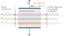
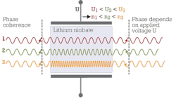
How does this help for phase modulation? Well, if n is a function of the strength of the field, then so is the speed and wavelength of the light traveling through the crystal. Thus, if we apply a voltage to the crystal, then the wavelength of the light crossing the crystal is reduced and we can control the phase of the exiting light by choosing the adequate voltage (see Figure 1).
In practice, this effect is used in so-called Mach--Zehnder modulators. Here, a light beam is split in two and one or both of the resulting beams travel through a phase shifting lithium niobate element such as we just described. Afterwards, the two signals have a phase difference ΔΦ that depends on the voltage difference ΔU between the two optical paths. Hence, when they're recombined, ΔU also determines if they interfere constructively or destructively.
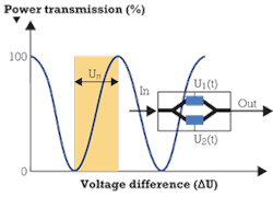
Figure 2 shows the block diagram and periodic relation between transmitted light power and ΔU. The half-wave voltage Uπ is the voltage needed for a phase change of π in power transmission, meaning the voltage difference between the modulator transmitting no power and transmitting 100% of the input power.
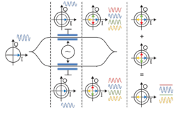
The phase shifting effects of a Mach--Zehnder modulator also can be depicted in an IQ diagram. In Figure 3, we take the example of a sine wave of constant amplitude and define relative phase Φ = 0. After the split of the signal, we have only half the power on each branch. In the blue example, there is no voltage applied to the modulator branches so the relative phase of the signals stays unchanged on both arms if they have equal length. After recombination, we again have the same sine wave with the original amplitude.
In the red example, the signal on the lower branch experiences a phase shift of π⁄2 and on the upper branch a phase shift of 3π⁄2 . In the green example, it's vice versa. Both examples have in common that when recombining the signals of both arms, they interfere destructively; the two vectors sum up to a zero vector. Therefore, in the red and green examples, we have no signal at the exit of the modulator.
In the case of the yellow signal, the Mach--Zehnder modulator's voltages are adjusted in such a way that on both branches the phase of the signal is shifted by π. When overlaying the two signals, we get a constructive interference. The resulting wave is a sine wave of the original amplitude shifted by Φ = π.
Mach--Zehnder modulator for transmission of a QPSK signal
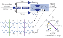
Now we'll see how the Mach--Zehnder modulator is used in a transmitter setup using QPSK modulation. In Figure 4, the complete block diagram is given along with a recap of the principles of the QPSK modulation we discussed in detail in the article "Which optical modulation scheme best fits my application?"
In QPSK modulation, we double the transmission rate relative to OOK by encoding 2 bits into one symbol. The four possible symbols are in the IQ diagram's four constellation points, which are all situated on the same circle. That means we operate with one amplitude only. The points are separated by π⁄2 .
In the transmitter, the electrical bit stream is split by a demultiplexer into the I and Q part of the signal. Each of the two parts directly modulates the phase of the laser signal on one arm of a Mach--Zehnder modulator. An additional Mach--Zehnder element shifts the phase of the lower branch, the Q branch, by π⁄2. After recombination of the two branches, we get the resultant QPSK signal as shown at the bottom of Figure 4.
Transmitters for more complex modulation schemes
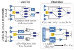
When it comes to higher-order modulation schemes like 16-QAM, the transmitter setup must be able to provide more amplitude levels and phases, which means higher complexity. In 16-QAM, each symbol encodes 4 bits and we need two optical power levels. To accomplish this, there are several approaches that differ in their modularity and in the level of performing the modulation in the electrical or optical domain. Figure 5 offers four implementation examples for comparison.
On the top left is a transmitter that consists of discrete components. The digital-to-analog conversion (DAC) is done on the optical signal. Using a BERT as an example, there are four output channels to electrically create the 4 bits of a symbol. The four voltages drive two Mach--Zehnder modulators. A laser source with a following splitter provides the two light signals that are then modulated by the Mach--Zehnder interferometers. On the lower branch, an optical attenuator follows to get the second lower light amplitude. The upper branch has another Mach--Zehnder element for shifting the phase relative to the lower branch. After recombination, we get the 16-QAM optical signal as the interference signal. The fact we need more than one Mach--Zehnder modulator is the weakness of this setup because they're expensive components. At the same time, the lithium niobate elements must have the same constant working temperature to enable precise phase control. That's difficult to guarantee.
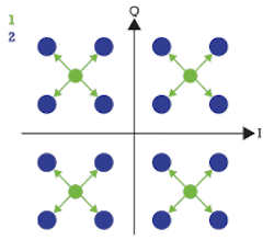
The phase would be easier to control if the Mach--Zehnder interferometers were integrated on one optical chip as in the example in the top right of Figure 5. Here, branches 1 and 2 are each emitting a QPSK signal. The interference result of both branches is the 16-QAM signal as shown in Figure 6. The drawback to this approach though is that it's not commercially available.
In the bottom left example of Figure 5, there are two designs where the DAC is performed in the electrical domain. We can use a standard pattern generator for creating the 4-bit sequences. The I part of the signal is on the upper two arms. An attenuator in one arm provides a second amplitude level. The same situation exists on the lower two arms where the Q part of the signal has its origin. After passing a combiner, the two-level electric signals control the optical signals of a Mach--Zehnder modulator. The disadvantage of this approach is that because of its many components the setup is very complex and therefore not flexible. It's also not possible to realize a higher-order modulation scheme like 64-QAM because the voltage resolution isn't good enough for more than two amplitude levels.
The bottom right example of Figure 5 shows the most convenient and flexible variant. The signal is modulated with an arbitrary waveform generator, which then drives a Mach--Zehnder interferometer. Using this setup, it's no problem to generate many more levels. We can think of far more complex modulation schemes than 16-QAM that may be common in the future and put into practice with this kind of optical transmitter.
So far our reflections have been on the transmitter side of complex modulated optical signals. Regarding the receiver side, we'll be learning more in the next tutorial.
*P.J. Winzer and R.J. Essiambre: "Advanced Optical Modulation Formats," IEEE Proceedings, 94(5), 2006. All other figures in this article are contributed by Oliver Funke, Stephanie Michel, Bernd Nebendahl, and René Schmogrow.
STEPHANIE MICHEL is technical marketing engineer in the Digital Photonic Test Division of the Electronic Measurements Group at Agilent Technologies. The Electronic Measurements Group will spin out of Agilent in November under the name Keysight Technologies.
Archived Lightwave Issues
