Forward error correction advances optical-network performance
The speed/power equation is a popular semiconductor benchmark because it provides a straightforward metric to gauge how process improvements affect device features. Semiconductors can generally achieve faster performance by increasing the electrical current. The quotient of these two characteristics (speed/power) results in a constant value. Process improvements that achieve more speed for a fixed amount of power consumption, or identical speed performance for less power consumption, improve the speed/power constant.
This metric provides an excellent way to measure the gains of a new process relative to an old one and also serves as a basis for historical performance. Most importantly, speed/power metrics can be combined with cost to provide justification for switching costs or capital expenditures.
Optical-networking equipment, on the other hand, transports bits from point A to point B and has features that allow this transport to take place in a reliable and flexible manner. The companies that buy this equipment purchase solutions that meet their feature, distance, and capacity requirements. Distance and capacity-the transportation of a given amount of bits a certain distance or transporting the most bits over a fixed distance-are what matter in the telecommunications universe. Therefore, distance-capacity is a useful baseline performance metric for optical-networking equipment.
Metrics such as distance-capacity allow the performance gains of new technologies to be quantified in a way that is independent of specific optical-link characteristics. Links may have different optical signal-to-noise ratio (OSNR) versus bit-error-rate (BER) characteristics, which don't allow direct comparison. Abstracting these characteristics with a metric like distance-capacity and factoring in cost allow quantification of the economic ramifications of new technologies. Forward error correction (FEC), one such technology, results in large increases of system OSNR without imposing huge costs and provides the features required for optical networks.
It is important to understand the factors that limit the distance-capacity product if this benchmark is to be improved. Capacity is a function of two variables: the number of wavelengths that can be carried via wavelength-division multiplexing (WDM) and the rate at which data is transmitted on these wavelengths. Increasing the capacity by adding wavelengths or increasing the serial bit rate will decrease the distance the link can span, assuming the optical parameters remain unchanged. Improving one factor-distance or capacity-will result in a reduction of the other factor, allowing the distance-capacity product to remain roughly constant. This is a result of optical noise effects limiting the performance of a given link.
Primarily, two effects limit optical links: "optical attenuation" and "dispersion." Optical attenuation is the loss of optical energy the signal experiences as it travels through optical fiber. In effect, the light transmitted gets "darker" the farther it is transmitted. Attenuation is measured in decibel units/km and is a function of the type and quality of fiber used.
Techniques such as WDM divide the output power of amplifiers among multiple channels-attenuating them further. If a 16-channel WDM system is converted to a 32-channel system, each of the signals is one-half the power of before, or more accurately, attenuated by 3 dB. There are limits to the optical-power output of these systems due to safety considerations. Therefore, adding WDM channels, or capacity, requires the signals to be re-amplified more often.
Dispersion also affects the optical signal by causing it to "stretch" and become less sharp. Ideally, a laser would emit light at a single precise wavelength, but that is not physically possible. What actually occurs is the laser source transmits a band of wavelengths centered on a desired frequency. Each of these wavelengths propagates at a slightly different speed, so the receiver sees a wider pulse than was transmitted, making the signal harder to resolve because the received data eye is less clear.
Dispersion is typically measured in picoseconds per kilometer and affects the capacity of a link. The bit "width" of a signal decreases as the throughput increases. A 2.5-Gbit/sec signal has a bit period of 400 psec, while a 10-Gbit/sec signal has a period of 100 psec. Therefore, a fixed dispersion value of 50 psec has greater effect on a 10-Gbit/sec signal than on a 2.5-Gbit/sec signal.
The effects of attenuation and dispersion are well understood and can be managed by engineering the specific link appropriately. To mitigate attenuation effects, system designers can add a regenerator, which uses a receiver to detect the optical signal, converts it back to an electrical impulse, and then drives a laser to re-amplify the signal. The length of the span between regenerators is limited by the sensitivity of the receiver. Regenerators could theoretically be daisy-chained ad infinitum until the necessary distance is reached. Recent advancements in dispersion-compensating fiber (DCF) allow fiber with various dispersion characteristics to be spliced together, reversing the effects of dispersion. Unfortunately, DCF causes much more attenuation than normal fiber, and its use will require additional optical amplification.
The development of the erbium-doped fiber amplifier (EDFA) has resulted in a shift away from regenerator-based optical-transmission systems to optically amplified systems. EDFAs allow the elimination of costly electrical regenerators while providing a flat gain region that spans approximately 20 nm. All light within this gain region is amplified, allowing several wavelengths within it to be optically amplified simultaneously. Hence, EDFAs are one of the main enablers of WDM.
Like all electrical amplifiers, optical EDFAs are not ideal and generate amplified spontaneous emission (ASE) noise. Using DCF to compensate for dispersion requires more EDFAs for amplification of the attenuated signal and results in more ASE noise in the link. ASE noise is the primary limitation of optical links that contain EDFAs.
Other nonlinear noise effects become more problematic as links reach tighter optical spacing and higher bit rates. High optical-power levers (compensating for DCF fiber or long spans) actually modulate the refractive index of silica fiber when varying the optical intensity due to the data being transmitted.
Four-wave mixing (FWM) is a particularly troublesome result of this effect in WDM systems. Three wavelengths on a fiber will mix to create a fourth wavelength at a frequency fnew where fnew = fl1 + fl2 - fl3. These fourth wavelengths appear right on top of an existing channel because typical WDM systems space the transmitted wavelengths at regular intervals-1540, 1541, 1542 nm, and so on. These new signals now overlay the original data, causing constructive and destructive interference. They also "steal" power from the fixed output power EDFA; an EDFA with an output power of 17 dBm will generate approximately 5 dB per channel in a 16-channel WDM system. FWM effects lower this per-channel power by forcing the generation of extra signals on new wavelengths. Dispersion helps reduce FWM. (Engineering dispersion out of a link with DCF will increase FWM effects.) Nonlinear optical effects such as polarization-mode dispersion (PMD), self-phase modulation (SPM), and scattering effects further complicate the engineering of effective optical links.
Compensating for one noise factor inevitably leads to increasing the effects of another or raising the cost of the system. New fiber types like nonzero dispersion-shifted fiber (NZ-DSF) reduce the effects of FWM but cost more than traditional fiber. Moreover, replacing existing fiber plants has steep economic penalties. Dispersion can be limited with DCF, but the additional EDFAs required add cost and noise, and FWM effects will become more apparent.
OSNR is an excellent way to provide an abstraction of all optical noise effects. The OSNR is the ratio between the received signal and the additive noise of the optical link. It provides the necessary summary of all the noise effects present on an optical link. Typically, the ASE noise of the optical amplifiers is the dominant component of OSNR. Nonlinear effects begin to play a role in high-channel-count 2.5- and 10-Gbit/sec systems.
There is a direct relationship between OSNR and BER. Higher OSNR leads to a lower BER. Optical-network operators want their networks to operate at low error rates and typically look for BERs on the order of 1x10-12 to 1x10-15. The required bit rate on a specific optical link can be extrapolated directly to a required OSNR. If the measured OSNR is higher than what is required for delivering the desired BER, additional margin exists in the optical link. This margin can be used to transmit more wavelengths, send signals over a longer distance, or increase the bit rate of the transported data, all of which improve distance-capacity.
The OSNR margin can also be "spent" to improve distance-capacity. Doubling the number of wavelengths decreases each wavelength's signal strength by a factor of 2 (-3 dB) because EDFAs have a fixed output power. If 3 dB of additional OSNR margin are available, this increased capacity can be made without exceeding the user's required BER. The additional OSNR margin might allow the installation of new EDFAs (more tolerance of ASE noise), which would make the attenuation effects of DCF acceptable. More OSNR provides increased tolerance for attenuation, allowing a link of a fixed bit rate and wavelength count to span a further distance. Higher tolerance for attenuation enables greater distance between EDFAs, so that a link of fixed capacity and distance with OSNR margin could use fewer EDFAs, thus increasing its reliability and decreasing cost.
There are competitive advantages to finding economical ways to improve OSNR. Multistage EDFAs, DCF, and NZ-DSF are all results of the enormous amount of effort being applied to this problem. These physical improvements lower the BER for a fixed distance-capacity link, yielding more OSNR.
Another solution provides improved OSNR by employing mathematics. FEC is a mathematical method by which data is encoded in such a way that upon receipt, all of the errors are detected and possibly corrected. Extra information is included, along with the original signal, to provide redundancy for correcting up to a specified amount of bit errors.
A good analogy is a noisy conversation in a restaurant, where every 10th word from the person speaking is inaudible. The listener still understands what the speaker is trying to say because information in their speech offers clues to the missing or garbled words. In a digital-communications system, FEC works the same way, allowing the receiver to "fix" errors based on additional information transmitted within the original data. Measurements of the BER outside the FEC link appear artificially high because the receiver transparently corrects the bit errors.
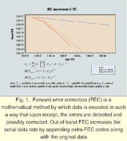
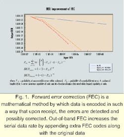
There are two types of FEC: in-band and out-of-band. In-band FEC embeds the codes into idle periods of the transmission. Synchronous protocols, such as Synchronous Optical Network/Synchronous Digital Hierarchy (sonet/ sdh), have a limited amount of idle period and therefore restrict the strength of the FEC algorithm (the number of errors that can be corrected before the decoder begins to fail). However, in-band FEC protocols have the advantage of not changing the serial bit rate or protocol and can be made interoperable with non-FEC systems.Out-of-band FEC increases the serial data rate by appending extra FEC codes along with the original data. It can provide unrestricted error-correction capability and is protocol-independent, making it a good choice for solving the BER problems of protocol-independent optical networks (see Fig. 1).
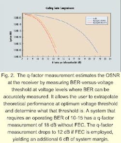
The q-factor measurement is widely accepted as a figure of merit for optically amplified systems. This technique estimates the OSNR at the receiver by measuring BER-versus-voltage threshold at voltage levels where BER can be accurately measured. (The voltage threshold is where a "1" becomes a "0.") It takes days to accurately measure a BER of 10-15, which is one bit error every five days in a 2.5-Gbit/sec link. The q-factor measurement allows the user to extrapolate theoretical performance at optimum voltage threshold and to determine what that threshold is. A system that requires an operating BER of 10-15 has a q-factor measurement of 18 dB without FEC. The q-factor measurement drops to 12 dB if FEC is employed, yielding an additional 6 dB of system margin (see Fig. 2).An additional 6 dB of OSNR gained through FEC would allow the doubling of WDM channel count (-3 dB) and a longer span distance, while maintaining the previous BER. Distance-capacity is improved by more than a factor of two with a relatively minor increase in semiconductor content. A more aggressive estimate of 6 to 8 dB of FEC improvement would support the upgrading of an OC-48 optical WDM link to OC-192 (10-Gbit/sec) rates, quadrupling the distance-capacity value.
The issue of providing optical-channel overhead (OCh-OH) while encoding and decoding a data stream for FEC purposes is a hot topic in interoperability forums. FEC requires the interleaving of additional coding bits among the original data. But the extra bits can also carry data. For example, the Lucent Digital Wrapper proposal and the VSC9210 provide multiple megabit-per-second data channels within the FEC link specifically for end-to-end operations, administration, maintenance, and provisioning (OAM&P) functions. Once available, this channel can be time-division multiplexed to provide discrete communication channels for various network-management functions.
Another important feature is the provision to track the quantity of errors that the FEC algorithm is correcting. This provision allows precise monitoring of the BER of an optical link, just like B1 and B2 BIP-8 parity allows monitoring in sonet/sdh. Unlike B1 and B2, however, the FEC algorithm itself is used to identify the signatures of bit errors to aid in identifying specific types of optical noise. This BER monitoring can provide a feedback loop to tune specific parts of the network. For example, a tunable laser source drifts over time-precise BER monitoring allows the wavelength to be tuned while FEC hides any resulting errors.
Because FEC is essentially an additional physical layer of the Open Systems Interconnection (OSI) model, it is important that its functioning is transparent to the transmitted protocols. Two critical specifications for FEC transparency are reframe time and algorithm latency. Reframe time is the time needed for an FEC algorithm to lock and begin decoding properly once it receives a compliant signal. Algorithm latency is the "propagation delay" through an FEC device-how much delay is added to a point-A-to-point-B connection when FEC is used. Existing sonet/sdh physical links have fixed requirements for reframe timing (<250 µsec) and ring protection switching (<50 msec). FEC algorithms with excessive latency or reframe timing will interfere with the transmitted protocols and existing systems.
Devices that implement FEC algorithms should have provisions for the FEC coding and interleaving of additional bits to be disabled, allowing signals to pass through untouched. Physical-layer devices such as clock-recovery should function at either traditional protocol line rates or rates multiplied by the FEC tax. The combination of these two features will allow interoperability with equipment that lacks FEC.
FEC is not a gimmick or a new phenomenon; it is used in many communications applications and for reliable data storage. The use of FEC in undersea telecommunications systems is quite common. The distances involved are thousands of kilometers and capacity must be maximized because of the high cost of undersea cable installation. Technology advances and their associated costs are ultimately judged by the improvements in equipment performance. FEC increases system OSNR, ultimately improving the distance-capacity performance of optical networks.
References:
10 Methods for Faster High-Speed Digital Communications Design, Hewlett-Packard Document number 6966-4258E (1998).
Thomas Fuerst, Key Considerations When Implementing OC-192 over DWDM Networks, Alcatel Telecom Inc. (1998).
Thomas W. Vislosky, System Issues Associated with Wavelength Add/Drop, Alcatel Telecom Inc. (1998).
Richard S. Vodhanel and John Gamelin, Large Channel Count WDM Systems: Trade-offs Between Number of Channels, Number of Spans, and Bit Rate, Tellium Inc. (1998).
Stephen Carlton, Forward Error Correction, Alcatel Telecom Inc. (1998).
Ivan P. Kaminov and Thomas L. Koch, Optical Fiber Telecommunications, Lucent Technologies (1997).
Andrew Schmitt is a telecommunications application engineer in the optical-networking product group at Vitesse Semiconductor Corp. (Camarillo, CA).


