Bidirectional-acting fiber components
Joseph kulakofsky
AT&T microelectronics
A single-fiber link, assisted by bidirectional-operating components, saves hardware, installation and maintenance costs
To enable optical fiber to gain installation cost parity with copper, manufacturers are developing bidirectional fiber-optic communications links that can handle single-fiber loop traffic between a central office and a neighborhood node near the subscribers. Additional savings in plant maintenance can result through reduction of the number of optical connectors in the single-fiber architecture.
Because optical fiber has been used mostly in office-to-office trunks, the volume of traffic carried has required multiple fibers. With these fibers, there was no reason to consider single-fiber bidirectional communications. As a result, the hardware only supported unidirectional transmissions where separate fibers carried upstream and downstream traffic.
The use of two unidirectional fibers and their supporting hardware can in some cases increase the cost of installation. If optical fiber is to replace copper in the loop, the cost of installation must be reasonably competitive with the cost of rehabilitating the existing copper plant.
A simple dual-fiber unidirectional communications link consists of two transmitters (each containing a laser), two optical fibers and two receivers (each containing a photodetector). These optical-electronic components usually come in four packages with individual connectors, or in transceivers with dual connectors or pigtails
A simple single-fiber bidirectional link also requires two transmitters with two lasers, and two photodetectors for two receivers. However, it requires only one fiber and only two transceiver assemblies, which significantly reduces materials and labor costs. However, these savings are partially offset by the need for a splitter at each end of the link.
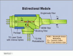
In simple form, the splitter can be considered a two-way mirror. Light launched by the laser should ideally pass through the splitter, and light received from the optical fiber should be reflected onto the photodetector. In practice, though, the two-way mirror is not perfect, and some of the light launched by the laser is reflected back into the interior of the housing. Also, some of the light received from the optical fiber passes through the splitter and impinges on the laser. Both phenomena can create serious problems that must be addressed during hardware design.
The splitter`s cost increases significantly as its performance increases. To minimize cost, a 3-decibel splitter is used in most bidirectional transmit/ receive assemblies. As its name implies, it reflects 50% of a light beam impinging upon it at a 45-degree angle. Thus, half the light generated by the local laser is launched into the optical fiber with the other half reflected into the assembly`s housing. Conversely, half the light received from the optical fiber is reflected onto the photodetector with the other half passing through the splitter and impinging onto the face of the laser.
Many communications system transmitters use a multiple quantum-well distributed-feedback laser. This type of laser is sensitive to externally generated light or reflections impinging on its face and, as a result, cannot be used with a 3-dB splitter. However, a Fabry-Perot laser is relatively immune to the effects of externally generated light impinging on its face and works well for basic telephone and telemetry applications. Thus, a Fabry-Perot laser-equipped single-fiber bidirectional link can serve as the basis for implementing fiber in the loop between the central office and remote terminals.
Numerous messages can simultaneously flow in both directions between the remote terminal and the neighborhood node drop point. If some of the light generated by the local laser reflects onto the local photodetector, then significant crosstalk can develop. To minimize errors and maximize satisfaction with the service, crosstalk must be kept to a minimum.
Limiting generated light
Special light-absorbing material applied to the inner surfaces of the electro-optical assembly`s housing can significantly reduce the amount of locally generated light impinging on the photodetector. Also, the amount of light generated by the local laser can be limited to the minimum intensity necessary to maintain reliable communications over the link. Even so, some crosstalk evolves if communications are being conducted through the link in both directions at the same time and wavelength.
Two approaches are used to eliminate crosstalk. One approach employs time-division multiplexing in which information alternately flows in one direction and then in the other direction. The other approach employs wavelength-division multiplexing in which communications flow continuously in one direction at one wavelength and simultaneously in the other direction at another wavelength. Each approach has advantages and disadvantages, but because implementation of fiber in the loop is just beginning, it is still not clear which approach will prevail.
In a bidirectional electro-optical assembly intended for use in a time-division multiplexing system, the laser and the photodetector operate at the same wavelength--typically 1300 nanometers. In this assembly, the laser emits light at 1300 nm while the wavelength of the incoming signal to the photodetector is centered around 1550 nm. Current technology dictates a need for separate laser and receiver packages for the 1550-nm transmitter at the other end. This setup is because of the emerging nature of uncooled 1550-nm laser technology, which does not yet permit the laser to be integrated into a bidirectional link. Therefore, a physically separate wavelength-division multiplexing coupler is needed to connect the separate transmitter and receiver to the fiber at this end of the link.
Aside from the laser and photodetector, a key difference between time-division multiplexing and wavelength-division multiplexing assemblies is the splitter. In the time-division multiplexing assembly, a conventional 3-dB splitter is used. In a wavelength-division multiplexing assembly, the splitter is a wavelength-sensitive filter that passes light at one wavelength while reflecting light at another wavelength. Although typically more efficient than a conventional splitter, some light generated by the laser is reflected back into the housing. Crosstalk resulting from these reflections can be reduced by placing a second filter over the photodetector to block light at the laser`s wavelength. This filter is needed because the photodetector is sensitive to the receive and transmit wavelengths.
Wavelength-division multiplexing filters cost more than simple 3-dB splitters. Also, 1500-nm optics typically cost more than 1300-nm equivalents. Thus, a wavelength-division multiplexing electro-optical assembly typically costs more than an equivalent time-division multiplexing assembly. However, because traffic continuously flows in both directions, the use of wavelength-division multiplexing eliminates the need in a time-division multiplexing system for circuits to control the flow of data back and forth through the fiber.
Taken at a systems level, the difference in the total cost between the two approaches is insignificant and, as a result, the choice between them must be based on other factors--the difference in the cost of maintaining spare parts inventories at one or two wavelengths, the ability to use the same electro-optical assembly at either end of the link and the relative performance and service life of optical devices at the wavelengths of interest.
Amplitude differences
The loop between a remote terminal and the final optical node point simultaneously handles communications for numerous subscribers. To facilitate delivery of information to the intended service drop, the information is carried over the fiber link in specifically addressed packets using an appropriate coding scheme. This scheme can create problems in the receiver if a standard, off-the-shelf AC-coupled circuit is used.
To appreciate the problem, consider the circuit`s data stream operation. In many cases, data is received at two amplitude burst levels. Their difference is a result of short- and long-path lengths between nodes and remote terminals.
The amplitude of the circuit`s slicing level--or peak detector output--generally changes. Only pulses with an amplitude greater than the slicing level appear as a logic one in the decision circuit`s output, thereby reducing the potential for data corruption resulting from extraneous noise pulses.
In an AC-coupled circuit, the slicing level responds to changes in the incoming signal`s amplitude at a rate determined by the coupling circuit`s time constant. Thus, even though there is a significant and rapid change in amplitude between the fourth and fifth data pulses, for instance, the change in the slicing level is too slow to accommodate it. As a result, the first bit of the lower level burst is lost, and the second bit is partially lost.
Until now, designers had no choice but to implement a DC-coupled packet receiver with discrete components because all the commercially available integrated receivers were AC-coupled. This situation changed with the latest integrated packet receiver circuit. With an optical dynamic range of 26 dB, this circuit can handle packets varying in amplitude by a 100:1 ratio and separated by less than 300 nanoseconds. It should simplify the implementation of a bidirectional single-fiber link using either p-type-intrinsic-n-type or avalanche diode photodetectors.
Implementation of a bidirectional fiber-optic communications link is relatively straightforward in an isolated point-to-point environment. However, it becomes complex when it serves as the loop between a remote terminal and an optical node. For example, such a loop ultimately connects a significant number of subscriber lines to the remote terminal. This means each loop incorporates a significant amount of hardware, the cost of which can figure prominently in the decision to implement fiber in the loop.
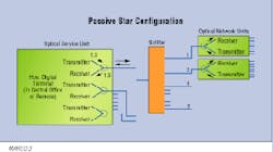
The two basic approaches to implementing a bidirectional fiber in the loop are the active and passive star configurations. The active star is a straightforward approach. Communications between the central office and a remote terminal are conducted over a pair of unidirectional optical fibers. The remote terminal communicates with a number of optical network units located throughout the area being served. These optical network units link the optical fiber with the copper wire drops used to connect subscribers to the telephone network. Communications between the remote terminal and each optical network unit is conducted through a single-fiber bidirectional link. However, this link requires a dedicated transmitter/receiver module in the remote terminal for each optical network unit supported.
Passive star approach
The passive star is an improved approach. Depending on how the passive star is implemented, the remote terminal function could be performed in a remote unit or in the central office, itself. Either way, it is connected to its optical network units through an optical splitter. Thus, a single transmitter/ receiver module can communicate with many optical network units. This setup results in hardware savings by eliminating numerous transmitter/ receiver modules in the remote terminal. Part of this savings is offset by the cost of the splitter. Even so, the net cost is often less than that of an equivalent active star.
The use of a passive star configuration divides the available optical power among all the optical network units connected to the splitter. This division may or may not be a problem, depending on the specifics of the implementation. For example, with the optical power split among 16 or more optical network units, the maximum distance between each unit and the splitter will be much less than in an equivalent active star. However, in a high-density service area in which many optical network units are located in a relatively small geographic area, the reduction in communications range that results from power sharing is probably of no concern. q
Joseph Kulakofsky is technical product support manager for AT&T Microelectronics in Santa Clara, CA.In a passive star configuration, a single transceiver in a remote terminal or central office communicates with many optical network units through a passive splitter. Although it is less hardware intensive than an active star configuration, the loss of a single headend transceiver affects more optical network units and the customers it serves.

