Bend matters, Part 2: Microbending in optical fibers
As we discussed in Part 1 of this two-part series, optical power loss is a significant determinant of network performance. Loss can come from a variety of sources, both environmental and man-made. One factor that can combine both environmental and human elements is bending.
Bending comes in two forms: macrobending and microbending. Macrobending has received significant attention in the media over the past few years as the new generation of “enhanced bending” fibers has reached the market. But microbending also can adversely affect optical power budgets, and requires the right combination of glass design and optical coating to overcome.
Microbending basics
Microbending attenuation of an optical fiber relates to the light signal loss associated with lateral stresses along the length of the fiber. The loss is due to the coupling from the fiber’s guided fundamental mode to lossy, higher-order radiation modes. Mode coupling occurs when fibers suffer small random bends along the fiber axes. This random bending is usually caused by external mechanical stresses against the cable material that compress the fiber. The result is random, high-frequency perturbations to the fiber (Figure 1).
contact with the fiber perturb it into small radius bends that can cause microbending.
Lateral stresses can be caused by pressure induced by manufacturing or installation or by temperature-induced dimensional changes in cabling materials that cause undesirable fiber/fiber or fiber/cable material interactions. These interactions can give rise to random microscopic bends or curvatures of <1-mm radius that create very small displacements of the fiber core from the fiber axis.
Microbending effects can be seen at all the commonly used wavelengths in singlemode fibers (1310, 1550, and 1625 nm), whereas macrobending effects are seen predominantly at 1550 and 1625 nm.
Microbending measurement
Minimizing microbending attenuation is critical to meet the bandwidth needs in today’s networks. Consequently, it is important to be able to characterize the degree of microbending sensitivity of commercially available optical fibers.
In 2001, the IEC established Technical Report TR62221, “Optical Fibres -Measurement Methods - Microbending Sensitivity,” which describes four test methods to characterize the microbending of fibers. IEC TR 62221 is currently under revision to update and improve the details of the test methods. The main revision objective is to provide the user with additional setup and apparatus details to enable more consistent characterization of microbending sensitivity. This may lead to future improvement in measurement reproducibility.
The four test methods referenced are:
- Method A Expandable Drum
- Method B Fixed Diameter Drum
- Method C Flat Plate
- Method D Basketweave.
Each of these methods attempts to induce a bend spectrum in a controlled and repeatable fashion suitable for laboratory use. The first three methods generate the bend spectrum caused by pressing a fiber against a rough surface. Methods A and B use drums coated with a material of fixed roughness, prescribed fiber winding tension, and controlled fiber winding pitch to prevent overlap. Method C sandwiches a short length of fiber between a lower rubber-surfaced flat plate, a wire mesh, and a top plate to which additional loading can be placed.
Method D uses fiber/fiber interaction and the dependence of microbending loss versus temperature. Method D makes use of fiber wound in opposite angles on succeeding layers on a silica drum, with controlled winding force, take-up width, take-up pitch, tapered stack, and wind speed.
Microbending testing according to IEC TR 62221 test methods is a valuable process by which optical fibers of different designs may be compared in a laboratory-style surrogate for optical cable testing. The methods are effective when making qualitative comparisons (i.e., ranking) among samples within a batch, especially when identifying fiber that is more suitable for cables with demanding attenuation requirements.
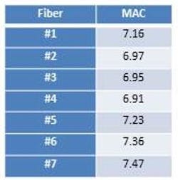
For example, seven fibers from a variety of commercial vendors were evaluated for microbending sensitivity as measured according to IEC TR62221 Method B.1 “MAC” is the ratio of mode-field diameter to cut-off wavelength, traditionally regarded as a good predictor of bend insensitivity; higher MAC values tend to be associated with greater macro- and microbending sensitivity.2 Table 1 shows some relative MAC values of commercially available fiber.
fibers evaluated for microbending
attenuation in different deployments.
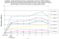
Method B was extended for this study to determine the attenuation response of the fibers throughout a temperature cycle from +20/-40/-60/+20oC (Figure 2). In general, the samples’ ranking in Figure 2 agrees with the MAC rankings in Table 1. For example, Fiber 7 has the highest MAC number and the largest attenuation increase during the experiment. Even so, some variability is apparent as Fibers 4 and 6, the samples with the smallest and second largest MAC numbers respectively, have virtually identical results. These samples have different coatings, which may explain the results.
and temperature cycle.
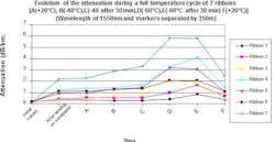
These fibers were then subjected to the same microbending deployment and temperature cycle after being made into encapsulated four-fiber ribbons (Figure 3). Each ribbon was produced from a single source fiber appearing in each of the four ribbon locations, i.e., Ribbon 1 is therefore a four-fiber ribbon with Fiber 1 and so on. The same in-line coloring and encapsulation process and materials were used for each ribbon. The attenuation response for each ribbon was determined as the average of the response of each of the four fibers.
B and temperature cycle.
There are many similarities between the ranking of the fiber samples and the ranking of the fiber in ribbon. The ribbon containing Fiber 7 showed the largest attenuation increase. The ribbons containing Fibers 1 and 2 showed the least.
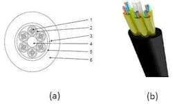
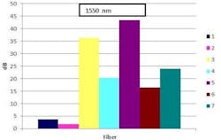
A 24-fiber composite fiber unit (CFU) mini-cable was produced as an example of a contemporary, constrained design with each fiber present in more than one cable position (Figure 4). The cable was subjected to a crush test according to IEC 60794-1-2 Method E3 with a force of 1000 N applied for 30 seconds, and the average attenuation increase was determined for each fiber in the study (Figure 5).
Again, there were many similarities between the fiber microbending results and the performance in the CFU during the crush test. For example, Fibers 1 and 2 continue to exhibit the smallest attenuation increases and Fiber 7 is among the highest. Some deviation in the correlation is also apparent, with Fibers 3 and 5 showing the highest attenuation in the crush test following a middle ranking in the microbending tests.
Coating as a microbend deterrent
The coating system employed for the protection of the glass has a significant role in the microbending sensitivity of fibers. In 1975, it was first reported that microbending losses could be reduced by combining a lower modulus primary coating of roughly 100 MPa with a harder secondary coating of roughly 1000 MPa.3 Since that time, the modulus of commercial primary coatings has been reduced by more than 100X to help enhance resistance to microbending. Recent developments in coating materials protect the low loss of advanced fiber designs with outstanding microbending resistance.
The right combination of fiber design and coating system can significantly improve optical loss from fiber bends, both from microbending as discussed here and from macrobending as discussed in Part 1 of this series. With fiber-optic networks becoming more essential to support critical communications from the core to the access, service providers must choose their fiber plant wisely to minimize optical power loss and maximize their network performance.
References
1. Arvidsson, B., et al., “Microbend evaluation of selected G.652D & G.657 fibers and ribbons before cabling,” The Proceedings of the 60th IWCS, 2011, Paper 3-5, page 61.
2. Unger, C., and Stöcklein, W., “Characterization of the bending sensitivity of fiber by the MAC-value,” Optics Communications 107 (1994) pp 361-364.
3. Gardner, W.B., and Gloge, D., “Microbending Loss in Coated and Uncoated Optical Fibers,” Topical Meeting on Optical Fiber Transmission, Williamsburg, VA (1975).
Ian Davis is strategic alliances manager at Corning Inc.
Steven Schmid is FOM global senior manager - applications development and technical services at DSM Functional Materials.


