Pulling the signal out of a coherent transmission isn't easy. Fortunately, technology has found the answer.
By STEPHANIE MICHEL
We found in the last part of our series on complex optical modulation, "How to detect complex modulated optical signals," that the most flexible detection setups are heterodyne time domain detectors, which are applicable for test and live signals and operate independent of the modulation format.
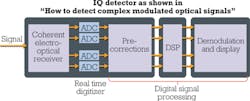
In Figure 1, such an IQ detector is positioned on the left side. You can also see that there are still some steps to take before the incoming bits encoded in the symbols can be identified and further processed. The receiver architecture shown here is recommended by the Optical Internetworking Forum (OIF) and enables extraction of all information in the signal. We'll examine receiver architecture in detail.
Relieving many impairments
After analog-to-digital conversion, digital signal processing (DSP) follows as an integral part of any coherent optical receiver. The use of DSP makes the big and attractive difference versus conventional on/off keying, where we have to worry about the signal-distorting effects of chromatic dispersion (CD), polarization mode dispersion (PMD), etc. DSP supports algorithmic compensation for CD, PMD, and other impairments, since coherent detection provides the complete optical field information. That means complex optical modulation relieves us from the need for PMD compensators or dispersion compensating fibers as well as the increase in latency induced by these modules.
An upstream pre-corrective step removes receiver imperfections. These imperfections can be channel imbalances between the four electrical channels, IQ phase-angle errors of the IQ mixer, timing skew between the four ADC channels, and a differential imbalance of the nominally balanced receiver. For removal of these impairments, the component is typically characterized over wavelength during the instrument calibration.
Apart from these imperfections introduced by the receiver, DSP has to compensate for the degradation the signal experiences on the optical path between transmitter and receiver. These are CD and PMD, polarization-dependent loss (PDL), polarization rotation or polarization state transformation (PST), and phase noise.
For estimating the impact of phase noise, the carrier phase can be tracked over time. Nevertheless, this step is not compulsory in a coherent receiver setup.
Carrier phase recovery
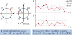
By introducing a local oscillator (LO), we found a way to track the signal's phase changes over time relative to the LO's phase. But the fact that the LO in a heterodyne receiver scenario has a different frequency than the signal causes a linear phase drift over time. That's understood when we remember in "How to detect complex modulated optical signals" we showed that in a heterodyne receiver IPhoto is proportional to cos (Δφ + Δωt). You can see this "rotating" constellation in Figure 2 for QPSK modulation.
For preventing ambiguities, the phase must not change faster than π/4 per symbol time, which is half the phase difference between two neighboring symbols. That in turn means the frequency offset between the LO and signal needs to be smaller than 1/8 of the symbol clock for QPSK.
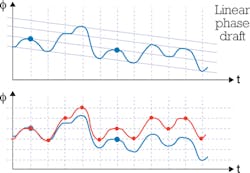
To be able to track the phase, the signal must be sampled at times with predictable phase values, for example, at the symbol times. For the case of a bandwidth-limited signal, the sampling rate of the phase is smaller than the symbol rate. In Figure 3 the red line shows that the phase may not be correctly recovered.
Under these circumstances, the carrier phase noise and offset must be within very tight limits to allow recovery of the phase. In a real transmission system, that's usually not the case since these tighter specifications aren't required in real line cards that use real time acquisition.
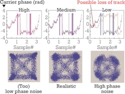
Figure 4 shows the influence of carrier bandwidth on phase recovery for a DFB laser. On the left is an example of a high tracking bandwidth. The constellation points in the IQ plot are artificially narrow because in this case phase tracking reduces the angular width of the symbols. At lower bandwidth, we get the more realistic looking round symbols. With even lower bandwidth, in the carrier phase plot we have reached a limit where it's not possible to track the phase anymore. The angular spread of the symbols is clearly affected by phase noise that could not be removed.
Finding the Jones matrix
Since we need to provide two independent baseband signals (for x and y polarization) to the digital demodulator, polarization demultiplexing is a fundamental step in DSP. In this step, we have to compensate for PMD and PDL and consider that in singlemode fibers the polarization state is not preserved during propagation.
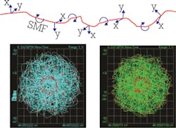
The polarization directions evolve along the signal's way through the fiber (see Figure 5) so that the state of polarization (SOP) at the end is not simply related to the orientation of the receiver. That's why, with the polarization beam splitter in the receiver, we do not get the two independent signals but a linear combination of the two polarization tributaries. Polarization maintaining fibers preserve the SOP but they're not deployed in data transmission due to their higher attenuation and price.
All the degrading effects that happen to the fully polarized light in the fiber channel can be mathematically described with a so-called Jones matrix. The sent signal S is multiplied with the Jones matrix, resulting in the received signal R. For an ideal channel without impairments, the Jones matrix is an identity matrix; the received signal is the same as the originally emitted signal (see Figure 6). In its most general form, the Jones matrix is a complex 2×2 matrix with eight independent real parameters.
So we basically need to find the Jones matrix to deduce the original signal from the measured received signal. That's hard to do since we usually have little to no information on the quantities of the impairing effects that the signal has experienced in the channel.
Therefore, so-called blind algorithms are often employed to approximate the original signal. These are estimation techniques that don't require knowledge of the original signal (except for the modulation format). Here, a series of equalizer filters (see Figure 7), applied to the received signal, represents the inverse of the Jones matrix. Each filter element models a signal degrading effect. The algorithm iteratively searches the set of filter variables (a, β, k...), which leads to convergence, meaning that the measured symbols map with minimal error to the symbols calculated by the algorithm.
A drawback to this method is that it may recover the same polarization channel twice. This problem is known as a singularity of the algorithm. It's also a very complex method because each symbol has to be treated individually to calculate the next iteration step.
Easier in Stokes space
The estimation gets easier in Stokes space, where polarization demultiplexing is truly a blind procedure because neither demodulation nor knowledge of the used modulation format or carrier frequency is required. Additionally, in Stokes space we don't face the singularity problem.
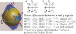
The Stokes space helps to visualize polarization conditions of optical signals and is therefore also a good tool for observation of polarization changes along an optical channel. Any polarization state of fully polarized light can be depicted by a point in this three-dimensional space that lies on the surface of a sphere - the so-called Poincaré sphere that has its center in the origin of the coordinate system. The radius of the sphere corresponds to the amplitude of the light. Circular polarization can be found along the S3 axis. Along the equator in the plane spanned by the S1 and S2 axes, we have linear polarization, and intermediate positions represent elliptical polarization. In Figure 8, we can see in green where some of the individual polarization states are situated on this globe.
Also in Figure 8, a measured x- and y-polarized QPSK signal is shown. There are four possible phase differences between the two signals at the sampling points. The combination of these x and y signals with these four phase differences gives the measured blue dot clouds in Stokes space. (With a QPSK signal in only one polarization direction, we would only get one accumulation on the S1 axis.)
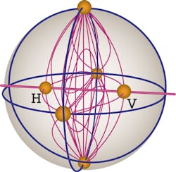
The transitions between the four states define a lens- like object in Stokes space (see Figure 9). It can be shown that polarization multiplexed signals of any format always define such a lens.
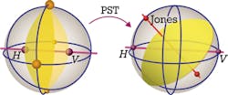
When we face PST along the optical path of a singlemode fiber, the lens is being rotated in the Stokes space (see Figure 10). From the rotation, we can deduce the Jones matrix, which is the normal of the lens-like object.
How are other signal-degrading effects represented in Stokes space? With PDL, the lens is deformed and shifted. Nevertheless, that doesn't cause a problem for recovering the Jones matrix. The deformation allows quantifying the amount of PDL. CD is polarization-independent and doesn't impede polarization demultiplexing. In this case, constellation plots are the preferable tool for a quantitative investigation.
Determination of the symbols
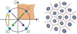
After successful DSP alongside polarization demultiplexing, we can finally decide the received symbols. In QPSK, the decision criterion is the I and Q value of the measured point in the constellation diagram (see Figure 11), e.g., every point with positive I and Q value will be interpreted as "11." In more advanced formats, it's no longer possible to simply take the I and Q values as decision levels. The points are assigned to the closest symbol. From the diffuse clouds on the right side of Figure 11, we can tell that even with coherent detection we still face bit errors. How can we quantify these?
That will be discussed in the next part of our tutorial series on coherent optical signals.
References
Figure 1 is courtesy of OIF Implementation Agreement for Integrated Dual Polarization Intradyne Coherent Receivers, IA # OIF-DPC-RX-01.2, Nov. 14, 2013. Figure 7 is courtesy of J.C. Geyer, F.N. Hauske, C.R.S. Fludger, T. Duthel, C. Schulien, M. Kuschnerov, K. Piyawanno, D. Van den Borne, E.-D. Schmidt, B. Spinnler, H. de Waardt, B. Lankl, and B. Schmauss, "Channel Parameter Estimation for Polarization Diverse Coherent Receivers," IEEE Photonics Technology Letters, Vol. 20, No. 10, May 15, 2008. All other figures are contributed by Todd Marshall, Stephanie Michel, Bernd Nebendahl, or Bogdan Szanfraniec.
STEPHANIE MICHEL is technical marketing engineer in the Digital Photonic Test Division of the Electronic Measurements Group at Keysight Technologies Inc. (formerly Agilent Technologies' electronic measurement business).
