by Daniel Mahgerefteh
For the past two decades, high–performance optical transmitters for 10–Gbit/sec telecommunications systems have relied upon external modulators to maintain signal integrity while achieving the reach necessary for these applications. The large size and high power consumption of these modulators, however, have left the door open for alternative approaches.Introduced in 2004, the chirp–managed laser (CML) is a compact, directly modulated laser transmitter that provides an alternative to externally modulated transmitters such as electro–absorption (EML) and Mach–Zehnder transmitters. CML is known for its ability to extend reach to 200 km in 10–Gbit/sec DWDM systems without requiring dispersion compensation. CML is also a competitive alternative to EML for 80–km DWDM and TDM applications and is completely interoperable with it.
Although CML and EML have different looking eyes as characterized by mask margin, they provide similar bit–error rate (BER) performance for 80–km applications and are both fully compliant with ITU standards. Specifically, CML trades off the higher mask margin of EML for higher dispersion tolerance while providing higher optical output power.
One of the key factors that determine dispersion limitations—and therefore maximum reach—is chirp, which is the change in instantaneousness frequency/wavelength of an optical pulse with time. Transient chirp occurs at bit transitions and can lead to pulse spreading or contraction after transmission in dispersive fiber depending on the sign of the chirp. Adiabatic chirp blue–shifts '1' bits relative to '0' bits. Most externally modulated transmitters, including EMLs, have transient chirp. However, directly modulated lasers generate both transient and adiabatic chirp.Externally modulated lasers typically use an external electro–absorption (EA) or LiNbO3 modulator to carve data into the output of a CW laser. EMLs actually use negative chirp to overcome dispersion limitations. Specifically, blue–shifted chirp at the falling edge travels faster than red–shifted chirp at the rising edge. As a result, the falling edge catches up to the rising edge and the pulse compresses. The overall BER can be improved by exploiting this compression up to a certain distance, after which the BER becomes progressively worse with distance.
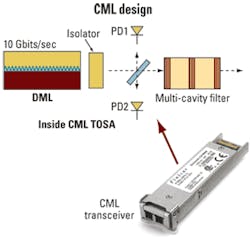
CMLs take a different approach to chirp (see Fig. 1). A CML comprises a high–speed, optically isolated distributed feedback (DFB) laser, passive optical spectrum reshaper (OSR) filter, and supporting optics.
Even though the laser in a CML is directly modulated, the CML is able to achieve significantly better dispersion performance compared to traditional directly modulated lasers (DMLs) that are limited to 5 km at 1550 nm in standard singlemode fiber. This is partly because a standard DML is biased close to the laser threshold current, thus generating large positive transient chirp that is detrimental to transmission performance. The laser in a CML, on the other hand, is biased high above the laser threshold current by about a factor of 5, and modulated with a small current swing that significantly reduces the transient chirp. The laser generates a small amplitude modulation at the output. The signal from the laser passes through the transmission edge of the OSR filter, which generates a high extinction ratio signal via frequency–to–amplitude modulation (FM to AM) conversion. Finally, the DFB wavelength is locked to the OSR and compensation is made for thermal chirp using a low–frequency circuit. The DFB's characteristics determine mode stability and wavelength tuning.CMLs achieve even more dispersion tolerance than standard externally modulated lasers through the use of destructive inter–symbol interference. Setting the adiabatic chirp to approximately half the bit rate (5 GHz at 10 Gbits/sec) causes '1' bits separated by an odd number of '0' bits to be p out of phase. The resulting destructive interference of '1' bits in the middle of '0' bit slots keeps the eye open after fiber dispersion.
Finally, because they do not require an external modulator, CML modules are also more compact and have higher optical power than EMLs. Most significantly, the CML reach can be extended to over 200 km at 10 Gbits/sec. They are also tolerant to both positive and negative dispersion and can enable phase coding like differential phase–shift keying (DPSK).
One of the reasons EML transmitters are popular is the relative ease with which engineers can achieve a wide open eye when performing mask tests. Performance in mask tests is measured by how large a box can be placed within the central opening of the signal's low pass filtered eye diagram without touching the edges of the eye. The low pass filter used for mask tests is a Bessel Thompson–type filter with ~7–GHz bandwidth.
Mask testing came from the ITU as a means for defining performance for transmitters and receivers. Specifically, if a system failed, running a mask test could help locate which end of the link was responsible for the failure. The mask serves as a minimum requirement for performance. If a transmitter fails the ITU minimum mask test, it is the likely source of errors.
To ensure sufficient performance, engineers introduce a margin for safety when they're designing transmitters, increasing the size of the box they want to see in the mask test. Increasing the box size by 20% from the minimum ITU requirement, for example, is thought to give that much more tolerance for error in other parts of the system.
The mask test, however, is only one of several metrics used to determine transmitter performance. The extinction ratio (ER) measures the difference from a '1' signal level to a '0' signal level. Back–to–back sensitivity determines the BER during a stress test. Dispersion penalty is the BER after the signal has traveled through fiber and determines how far a signal can travel reliably (i.e., reach). The bottom line metric for a transmitter, however, is its BER performance.
There is a common impression that the mask margin test provides a linear indication of the BER performance. In fact, additional mask margin past a certain point offers only diminishing benefit. When the eye is nearly closed—i.e., near the ITU minimum limits—sensitivity begins to drop sharply with worsening mask margin. Under these circumstances, the BER will begin to show a corresponding decline in performance. When there is excessive margin in the mask test, however, this means that the eye is more open but not necessarily that sensitivity will be correspondingly better.
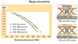
Consider the graph in Fig. 2, which shows an EML transmitter with 26% margin compared to a CML transmitter with 18% margin. Certainly, the eye with a 26% margin looks more open. However, the sensitivity of the two transmitters is equivalent as is their BER performance through 100 km of fiber (1,600 psec/nm). This shows that extra mask margin does not materially increase sensitivity.
The difference between the numbers 18% and 26% is not accidental. Achieving a 26% margin with an EML transmitter is actually reasonable to expect without a lot of extra work. This arises from the fact that EMLs are designed to have excess bandwidth available.
Transmitter bandwidth is inversely related to its rise/fall time. Consider a 100–psec time slot during which the transmitter can send a '1' or '0' bit. Bandwidth determines how long the bit is held at the '1' level. For example, with a transmitter with fast rise/fall time, the pulse could rise to level '1' in 10 psec, hold for 80 psec, then fall in 10 psec. A transmitter with a slower rise/fall time might take 30 psec to rise, leaving 40 psec for holding and 30 psec to fall.
Receivers determine the bit level by integrating the energy sent over the bit period. The bandwidth of the receiver is designed to capture the transmitted signal with minimal distortion while also minimizing input noise. Higher receiver bandwidth enables faithful discrimination of '1' levels from '0' levels (i.e., higher bandwidth at the receiver reduces inter–symbol interference [ISI]). However, higher bandwidth also means more noise input, which degrades BER. The optimum bandwidth for a receiver is therefore limited to ~75% of the bit rate, so 7 to 8 GHz for a 10–Gbit/sec NRZ signal.
A transmitter with faster rise and fall times will result in a more widely open eye but will not necessarily result in better discrimination of the '1' and '0' levels or better BER sensitivity because of the limited receiver bandwidth. There is minimal difference between BER sensitivity for a transmitter with rise and fall times of 10 psec compared to one with 30–psec rise and fall times. Thus, the extra margin of an EML transmitter that is achieved because of its excess bandwidth does not provide a realistic performance comparison to CML. Again, mask tests were designed to determine minimum performance to identify the source of errors in a link. Thus, the more relevant measurement for real–world link performance is sensitivity of the signal before and after it has passed through fiber.
CML transmitters have little excess bandwidth and meet the Nyquist criterion, having the minimum bandwidth required for no inter–symbol interference at the transmitter output. This means that the rise and fall times are longer than an EML's and on the order of ~30 psec, making it difficult to achieve a 26% margin. The upside of not having excess bandwidth for a CML is dispersion tolerance margin after fiber transmission. The CML with 18% mask margin still transmits error–free after 120 km, while the EML with 26% mask margin generates an error floor at that distance.
So while the eye of an EML transmitter at 26% may look "better" than the eye of a CML transmitter at 18%, their sensitivities after traveling through fiber are equivalent at 100 km and much better for CML at 120 km. Using mask as a measure of performance is similar to trying to determine the speed of two race cars by comparing how clean their engines appear rather than by which of them crosses the finish line first.
CML and EML transceivers are interoperable. Both transceivers use the same receiver component technology of p–i–n or avalanche photodiode. Therefore, interoperability between CML and EML is tested by focusing on the setting of the receiver decision threshold; this is the level above which the receiver takes an incoming signal to be a '1' and below which it takes it to be a '0.' Given that the EML is the incumbent technology, interoperability is measured by how well a receiver having a decision threshold optimized for EML responds to a CML–transmitted optical signal.
Let's look again at Fig. 2, which shows a comparison of an EML transmitter with a 26% mask margin vs. a CML transmitter with 18% mask margin. Note that this test was conducted under worst–case conditions for the CML: The receiver decision threshold was optimized for the EML through 100 km of fiber. As shown, the CML and EML have the same back–to–back sensitivity and same dispersion penalty after 100 km. This interoperability test shows that CML transceivers are appropriate for use in networks having installed EML transceivers. Although CML is a different technology than EML as marked by their different–looking eyes, it is interoperable with it. Also, the highly visible excess mask margin of EML compared to CML does not translate into a substantial difference in their BER performance up to 100 km.
In the final analysis, both EML and CML technologies provide an excess: EML an excess of mask margin and CML an excess of reach. For 80–km applications, the excess in either case is superfluous. Both technologies meet ITU standards with expected dispersion (<2 dB) at this distance.
The question for developers is where they would rather place that excess margin. With EMLs, excess margin results in a cleaner eye diagram beyond what is needed to make sure bits arrive intact. CMLs trade off some of that excess mask margin in favor of better dispersion penalty margin. At the receiver, where the eye diagram truly counts, a CML delivers a clean eye while the excess dispersion penalty enables longer reach, just in case it's needed (i.e., either the fiber has higher dispersion than expected or the network is expected to scale in the near future).
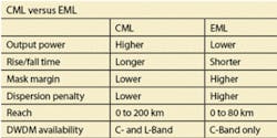
When it comes to standard 80–km DWDM and TDM links, EMLs and CMLs are equally applicable. However, for many applications CMLs offer several advantages compared to EMLs (see Table):
- The CML's extended reach provides a scalability advantage by supporting the next step in reach, 120 km, as well as out to >200 km;
- While EMLs are available only in the C-Band, CMLs support all DWDM wavelengths in both the C- and L- Bands;
- CMLs are also available in a narrowingly turnable (50-GHz channel spacing) XFP form factor. This not only lowers inventory management costs, but also increases the predictability of wavelength availability; and
- CMLs support higher output power. This extra power enables CML-generated signals to be able to tolerate more loss in the fiber.
Daniel Mahgerefteh is director technology at Finisar Corp. (www.finisar.com).


