Network design and installation considerations
Network design and installation considerations
Designing premises networks to tia standards requires careful consideration. The first of a two-part series.
Dion King, Siecor Corp.
One of the most challenging decisions a telecommunications manager can make is choosing the proper design for an optical-fiber cabling plant. Optical-fiber cable, which has extremely high bandwidth, is a powerful telecommunications medium that supports voice, data, video, and telemetry/sensor applications. However, the effectiveness of the medium is greatly diminished if proper connectivity is not designed into the system. Such connectivity allows for flexibility, manageability, and versatility of the cable plan.
The traditional practice of installing cables dedicated to each new application is all but obsolete. Instead, designers and users alike are learning that proper planning of a structured cabling system can save time and money. For example, a cable that is installed for point-to-point links should also meet specifications for later upgrades as it becomes part of a much larger network. Thus, anticipating future applications and providing additional fibers for unforeseen applications and for interfacing with local service providers can avoid duplication of cable, connecting hardware, and installation labor.
A structured cabling design that uses a physical hierarchical star topology offers a communications transport system that can efficiently support all logical topologies (point-to-point, star, ring, and bus). The guidelines presented here follow the general recommendations set forth by the tia/eia-568A Commercial Building Telecommunications Cabling Standard. This article will begin with an overview of the different logical topologies commonly used today. A discussion of the physical implementation of these logical topologies in the different premises environments (campus backbones, building backbones, and horizontal cabling) will follow. In the context of this article, the term "logical topology" refers to the method by which different nodes in a network communicate with one another. It involves protocols, access, and standards-based applications at the electronic circuit level. "Physical topology" simply refers to the physical arrangement of the cabling or cabling system by which nodes are attached.
Logical topology
To be universal for all applications, a structured cabling plan must support all logical topologies. These topologies define the electronic connection of the system`s nodes. Fiber applications can support point-to-point, star, ring, and bus logical topologies.
Point-to-point logical topologies are still common in today`s customer premises installations. Two nodes that require direct communication are directly linked by the fibers, normally a fiber pair (one to transmit, one to receive). Common point-to-point applications include Fibre Channel, terminal multiplexing, satellite up/down links, Escon, and telemetry/sensor applications.
A star logical topology is an extension of the point-to-point topology. This is a collection of point-to-point topology links, all of which have a common node that is in control of the communications system. Common star applications include
a switch, such as a private branch
exchange (pbx), Asynchronous Transfer Mode (atm), or data switch,
a security video system with a central
monitoring station,
an interactive videoconference system
serving more than two locations.
The ring logical topology, which is very prevalent in the data communications area, is supported by two primary standards: Token Ring (ieee 802.5) and Fiber Distributed Data Interface (fddi--ANSI X3T9). In this topology, each node is connected to its adjacent nodes in a ring. The nodes can be connected in single or dual (counter-rotating) rings. With counter-
rotating rings (which are the most common), two rings transmit in opposite directions. If one node fails, one ring will automatically loop back on the other, allowing the remaining nodes to function normally. This requires two fiber pairs per node rather than the one pair used in a simple ring. fddi networks typically use a counter-rotating ring topology for the backbone and a single ring for the horizontal.
The bus logical topology is also used for data communications and is supported by the ieee 802.3 standards. All nodes share a common line. Transmission occurs in both directions on the common line rather than in one direction, as on a ring. When one node transmits, all the other nodes receive the transmission at approximately the same time. The most popular systems requiring a bus topology are Ethernet, the Manufacturing Automation Protocol, and Token Bus.
Physical topologies
All of the logical topologies noted earlier are easily implemented with a physical star cabling scheme as recommended by the tia/eia-568A Commercial Building Telecommunications Cabling Standard. Implementing logical point-to-point and star topologies on a physical star is straightforward.
While data networks that use bus or ring topologies dominate the market--i.e., Ethernet, Token Ring, and fddi--the benefits of physical star cabling have led electronics vendors and standards bodies to develop electronic solutions designed to interface with a star network. These applications are typically implemented with an "intelligent hub" or concentrator. This device establishes the bus or ring in the backplane of the device and the connections are made from one or more central locations. Therefore, from the standpoint of a physical connection, these networks appear to be a star topology and are best supported by a physical star cabling system.
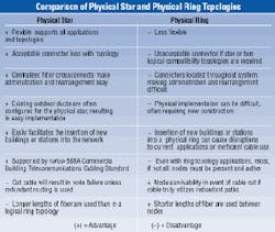
There are some situations where a physical ring topology would seem appropriate. But as can be seen in the table, which compares an optical-fiber physical star topology to a physical ring topology, the former is the best topology for
supporting the varied requirements of a structured cabling system.
Regardless of the topology, the network must be made reliable. As protection against system downtime, many systems employ redundant devices coupled to fibers in the same cable. The redundant system takes over immediately upon failure of the primary system, protecting against active device failure, although it does not help in the rare instance of a complete cable cut. However, the ultimate protection against system downtime is achieved through redundant routing. Redundant fibers are placed in a second route to immediately take over in the event a cable is damaged. Redundant routing should be considered when zero downtime for the physical cabling plant is required.
Physical star implementation
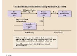
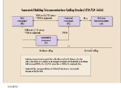
The more important recommendations of the tia/eia-568A standard as they relate to optical fiber and topologies are summarized as follows. The standard is based on a hierarchical star for the backbone and a single star for horizontal distribution (see Fig. 1).
The rules for backbone cabling include a maximum distance between the main crossconnect (MC) and the horizontal crossconnect (HC) of 2000 m for 62.5/125-micron multimode fiber and 3000 m for singlemode fiber. A maximum of one intermediate crossconnect (IC) should be positioned between an HC and MC. The MC is allowed to provide connectivity to any number of ICs or HCs, and the ICs are allowed to provide connectivity to any number of HCs.
The standard does not distinguish between campus (outside) and building (inside) backbones since these are determined by the facility size and campus layout. However, in most applications, one can envision the MC-to-IC connection being a campus backbone link and the IC-to-HC being a building backbone link. The exceptions to this would be major high-rise buildings in which the backbone may be entirely inside the building or a campus containing small buildings with only one HC per building, thereby eliminating the requirement for an IC.
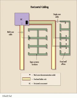
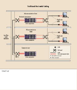
The horizontal cabling is specified to be a single star topology linking the horizontal crossconnect closet to the work-area telecommunications outlet with a distance limitation of 90 m (see Fig. 2). This distance limitation is not based on fiber capabilities but rather on copper distance limitations to support data requirements. The tia has published telecommunications systems bulletins tsb-75 and tsb-72, which allow the better use of optical fiber`s superior performance characteristics in horizontal applications. These publications cover the multi-user outlet and centralized optical-fiber cabling, respectively.
568SC polarity
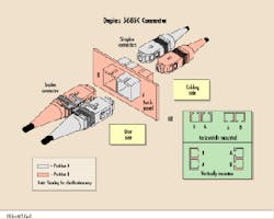
The simplex SC connector and adapter are keyed to ensure the same orientation of the connector upon mating. Upon installation of the duplex yoke that makes two simplex SC connectors into one duplex 568SC, the keying establishes the orientation of one fiber to the other (polarity) because the 568SC connector can only insert into the adapter in one direction. The two connectors are now labeled as position A and position B (see Fig. 3). It is important to note that the 568SC connector does not ensure correct polarity by itself.
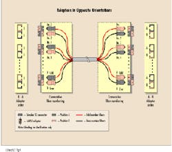
To achieve transmit-to-receive polarity in an optical network, an odd number of cross-overs must occur. A duplex fiber circuit is composed of two fibers and is installed to pair an odd-numbered fiber with the next consecutive even-numbered fiber (1 with 2, 3 with 4). To achieve transmitter-to-receiver connectivity, the odd numbered fiber, if connected to the transmitter on one end, must connect to the receiver on the other end. The specified 568SC adapter performs a cross-over in and of itself, i.e., Position A to Position B. Therefore, if all patch cords and the cabling plant are duplexed, there will always be an odd-number of cross-overs. An even number of cross-overs is impossible, as it would cause a transmitter-to-transmitter connection.
Polarity is managed at the patch panel or outlet. Based on the orientation of the adapter in the panel, the connector can either be installed in an A-B orientation or a B-A orientation (again, see Fig. 3).
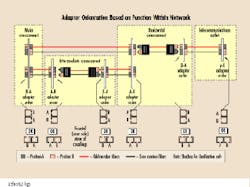
If the adapters are installed in opposite orientations on each end of the link (see Fig. 4), the installer still connects the fiber to the patch panel or outlet in a normal manner--counting from top to bottom, left to right. However, on one end, fiber 1 is in position A and on the other end it is in position B and so forth for the other fibers. Additionally, the tia/eia-568A recommends the proper orientation of each adapter in the network based on whether it is at the main, intermediate, or horizontal crossconnect, or at the outlet (see Fig. 5).
Campus backbone
The campus backbone cabling is the segment of the network that typically presents the designer and user with the most options, especially in large networks such as those found at universities, large industrial parks, or military bases. The campus backbone is also typically the most constrained by physical considerations such as duct availability, right-of-way, and physical barriers. For this reason, this section will present a number of options.
In smaller networks (both in number of buildings and geographical area), the best design involves linking all the buildings requiring optical fibers to the MC. The crossconnect in each building then becomes the IC linking the HC in each building to the MC. The location of the MC should be in close proximity to (if not collocated with) the predominant equipment room, data center, or pbx. Ideally, the MC is centrally located among the buildings being served, has adequate space for the crossconnect hardware and equipment, and has suitable pathways linking it with the other buildings. This network design would be compliant with the tia/eia-568A standard. Some of the advantages of a single hierarchical star for the campus backbone include the following:
It provides a single point of control for
system administration.
It allows testing and reconfiguration of
the system`s topology and applications from the MC.
It enables easy maintenance for security
against unauthorized access.
It allows graceful change.
It easily accommodates the addition of
future campus backbone links.
Larger campus networks (both in number of buildings and geographical area) may require a two-level hierarchical star. This design provides a campus backbone that does not link all the buildings to the MC. Instead, it uses selected ICs to serve a number of buildings. The ICs are then linked to the MC. This option may be considered when the available pathways do not allow for all cables to be routed to an MC or when it is desirable to segment the network because of geographical or functional communication requirement groupings. In large networks, this often translates to a more effective use of electronics such as multiplexers, routers, or switches to better utilize the bandwidth capabilities of the fiber or to segment the network.
No more than five ICs should be used unless unusual circumstances exist. If the number of interbuilding ICs is kept to a minimum, the user can experience the benefits of segmenting the network without significantly sacrificing control, flexibility, or manageability. When such a hierarchical star for the campus backbone is used, it is important that it be implemented via a physical star in all segments. This ensures that flexibility, versatility, and manageability are maintained.
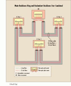
However, there are two main conditions under which the user may consider a physical ring for linking the interbuilding ICs and MC. These are: when the existing conduit supports it, or when the primary (almost sole) purpose of the network is fddi or Token Ring. Connecting the outlying buildings in a physical ring is seldom recommended. The ideal design for a conduit system that provides a physical ring routing would dedicate x number of fibers of the cable to a ring and y number of fibers to a star by expressing (not terminating) fibers through the ICs directly back to the MC (see Fig. 6). This allows the end-user the best of both ring and star topologies, although the design requires a more exacting knowledge of present and future communications requirements.
Building backbone
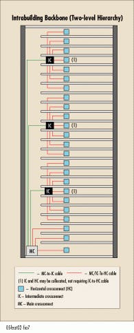
The building backbone design between the building crossconnect (MC or IC) and the HC is usually straightforward, though various options sometimes exist. Siecor recommends a single-hierarchical star design between the building crossconnect and the HCs. The only possible exception occurs in an extremely large building, such as a high rise, where a two-level hierarchical star may be considered (see Fig. 7). The same options and decision processes apply here. Sometimes, building pathways link HC to HC in addition to IC to HC, especially in buildings with multiple HCs per floor. Only in rare applications should a user design an HC-to-HC link. For example, this pathway might be of value in providing a redundant path between HC and IC, although a direct connection between HCs should always be avoided.
Horizontal cabling
The benefits of fiber optics (high bandwidth and low attenuation and system operating margin) allow greater flexibility in cabling design. Because of the distance limitations of copper and its small operating margin, passing data over unshielded twisted-pair cable (utp) requires compliance with stringent design rules. In addition to the traditional horizontal cabling architecture, optical fiber supports designs specifically addressing the use of open systems furniture and/or centralized management.
The traditional network design consists of an individual outlet for each user within 300 ft of the telecommunications closet. This network typically has data electronics equipment (hub, concentrator, or switch) located in each telecommunications closet within the building. Because electronics are located in each closet, this network is normally implemented with a small-fiber-count backbone cable (12- or 24-fiber count). This network uses a single cable per user in a physical star from the HC to the telecommunications outlet (see Fig. 8).
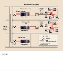
For open-systems furniture applications, a multi-user outlet network is best. The multi-user outlet calls for a high-fiber-count cable to be placed from the closet to an area in the open office where there is a fairly permanent structure, such as a wiring column or cabinet, in a grid-type wiring scheme. At this structure, a multi-user outlet, capable of supporting 6 to 12 offices, is installed instead of individual outlets (see Fig. 9). Fiber-optic patch cords are then installed through the furniture raceways from the multi-user outlet to the office area. This allows the user to rearrange his furniture without disrupting or relocating the
horizontal cabling. This type of network is supported in Annex G of tia/eia-568A, with more specific details published in tsb-75, "Additional Horizontal Cabling Practices for Open Offices."
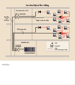
Centralized optical-fiber cabling is intended as a cost-effective alternative to the optical horizontal crossconnect when deploying 62.5-micron optical-fiber cable in the horizontal in support of centralized electronics. While Category 5 utp systems are limited to 100 m total length and require electronics in each closet for high-speed data systems, fiber-optic systems do not require the use of electronics in closets on each floor and therefore support a centralized cabling network. This greatly simplifies the management of fiber-optic networks and enables more efficient use of ports on electronic hubs and easy establishment of work group networks. Centralized cabling provides direct connections from the work areas to the centralized crossconnect by allowing the use of pull-through cables, or a splice or interconnect in the telecommunications closet instead of a horizontal crossconnect. While each of these options has its benefits, splicing a low-fiber-count horizontal cable to a higher-fiber-count building backbone cable in the telecommunications closet is often the best choice (see Fig. 10). This type of network is supported by the tia with details published in tsb-72, "Centralized Optical Fiber Cabling."
Equipment room(s) and network
interface cabling
As discussed in the campus backbone section, the MC is ideally collocated in the equipment room with the pbx, data center, security monitoring equipment, or other active equipment being served. However, physical constraints sometimes make this impossible, such as when multiple equipment rooms are being served and are not centralized. The MC does not have to be with any equipment room, and its location may be based entirely on geographic and physical constraints, e.g., duct space and termination space. There should be only one primary MC. Connection to the equipment room(s) can then be provided either with fibers in separate sheaths or combined with the backbone fiber cables.
For ultimate flexibility, manageability, and versatility of the fiber network, all backbone cables and links to equipment room(s) should be terminated at the MC. Fibers can be crossconnected to the required equipment room on an as-needed basis with the simple installation of a jumper. If there are link loss concerns, security concerns, or cost issues, selected fibers can be spliced through the MC to specific equipment rooms. While this forfeits a degree of flexibility, as long as all of the cables come to the MC, the routing can be changed by altering the splice plan.
The same location considerations apply to the MC network interface when contracted services are provided by a local common carrier, long-distance company, or bypass company. The designer/user should bear in mind that when these services are provided via optical fibers, the fibers will almost certainly be singlemode. u
Dion King is a senior systems engineer at Siecor Corp. (Hickory, NC). He is a member of bisci and the Institute of Electrical and Electronics Engineers, as well as a registered communications distribution designer (rcdd). He is also a contributing author of Handbook of Optoelectronics for Data Communication.Fig. 9. The multi-user outlet design calls for a high-fiber-count cable to be run from the closet to an area in the open office where there is a fairly permanent structure. Here, a multi-user
outlet capable of supporting 6 to 12 offices is installed instead of individual outlets.Fig. 10. Centralized cabling provides direct connections from the work areas to the centralized electronics. Splicing a low-fiber-count horizontal cable to a higher-fiber-count building backbone cable in the telecommunications closet is often the best choice for such connections.
