Carrier Ethernet transport: No longer 'if,' but 'how'
For many service providers, it is no longer a question of whether to use Ethernet for transport; it is now a question of how to use it.
By Brian Pratt, Meriton Networks
It's been almost two years since the concept of connection-oriented Ethernet, including what is now known as Provider Backbone Bridging-Traffic Engineering (PBB-TE), was introduced as a serious alternative to SONET/SDH and MPLS for service provider transport networks. The notion of Ethernet as a transport technology has caught on quickly among service providers worldwide, in part because the economics and simplicity of Ethernet are easy to accept. And the quality of service (QoS) and sub-50 msec protection switching capabilities that PBB-TE adds to Ethernet make it a very attractive technology for transport. Indeed, for many service providers, it is no longer a question of whether to use Ethernet for transport; it is now a question of how to use it.
As more and more service providers look at evolving their transport networks to this technology, three key questions are emerging:
- If a provider opts for connection-oriented Ethernet, does that mean its transport network will be or should be an all-Layer 2 switched network?
- Is connection-oriented Ethernet supposed to replace the service provider's MPLS network?
- What are the management options for a connection-oriented Ethernet transport network? In particular, what are the control plane options?
The Ethernet transport network: All Layer 2 switched or not?
It may seem odd to suggest that an Ethernet transport network might not necessarily be a Layer 2 switched network. However, there are some very compelling reasons why Layer 1 and even Layer 0 transport and switching play a complementary role to Layer 2 switching in connection-oriented Ethernet networks. Indeed, this is exactly the concept of Carrier Ethernet Transport (CET).
There are several examples of past networking technologies where the client interface to the network was not necessarily the same as the technology used to switch and transport it. Going back to X.25 in the 1980s, the standards of that time only specified the X.25 interface to the network, leaving the service providers to decide which transport and switching technology to use within the X.25 cloud. Similarly, many Frame Relay systems used ATM transport switching among Frame Relay nodes. And now PBB-TE is following a similar route.
In CET, the term "service mapping" is used to describe this concept: The idea that, on a tunnel-by-tunnel or service-by-service basis, connection-oriented Ethernet (e.g., PBB-TE tunnels) can be mapped to one of three available switching and transport technologies:
- A Layer 2-based PBB-TE tunnel switching fabric.
- A Layer 1 Optical Transport Network (OTN)/Generic Framing Procedure (GFP)-based aggregation, switching, and transport subsystem.
- A Layer 0 WDM-based switching and transport subsystem that is multidegree, either reconfigurable optical-electrical-optical (OEO) or reconfigurable optical add/drop multiplexed (ROADM).
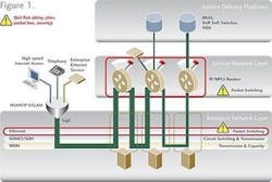
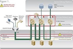
What is the rationale for this architecture? Consider the following network.
The starting point for many service providers is a blurry boundary between the IP/MPLS service network and transport. Many use the transport layer as "dumb pipes" between MPLS routers. There is no attempt to use any intelligence in the transport network to avoid "tromboning" all traffic to the MPLS routers, regardless of whether it is destined for service processing or it is transit traffic that the router will simply forward on.
Clearly, this network architecture unnecessarily wastes precious and expensive MPLS router port and switching resources, adding packet switching hops to the traffic for additional QoS risk (delay, jitter, packet loss, and security).
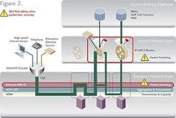
The first step toward improving this situation involves more intelligent planning of tunnels in a connection-oriented Ethernet transport network (PBB-TE), as shown in the following diagram.
Service layer resources can now be bypassed, leading to an overall reduction in total cost of ownership (TCO) and lower QoS risk. As traffic traverses each node in the CET network, Layer 3 processing at transit nodes can be avoided. This has the highly desirable effects of:
- Reducing the amount of transit traffic that may be needlessly processed by an MPLS router, allowing routers with smaller switching fabrics to be used.
- Reducing the number of relatively expensive Gigabit Ethernet (GbE) or 10GbE ports required on the MPLS router.
- Reducing the number of packet switching hops end-to-end for improved QoS (less delay, less jitter, less packet loss, and better security).
PBB-TE provides an ideal common client and provisioning interface for all kinds of traffic and potentially all ingress traffic to the transport network. The goal of PBB-TE is to traffic engineer the various Ethernet tunnels in the transport network such that Layer 2 packet switching (i.e., Ethernet frame switching) can be used to provide QoS that is literally as deterministic as if the traffic were transported by a SONET/SDH network. This includes QoS parameters such as throughput, delay/jitter, packet loss, and security.
However, as anyone who has engineered an MPLS network knows, Layer 2 is still packet switching. If used alone, Layer 2 provides a common switching resource for handling everyone's traffic via statistical multiplexing. If, for any reason, that switching resource becomes distressed, everyone's traffic can be affected.
For example, if sufficient traffic is sent to the switching resource to overload it (i.e., flooding it such that it cannot handle all traffic at 100% utilization), queues grow, and delay and jitter become more variable and increase. In severe distress (lasting for longer than an instant in time), queues overflow and packets are dropped. This results in deterioration in the quality of VoIP calls, audio or video glitches in IPTV services, and reduced throughput and response time for a whole plethora of other enterprise and residential broadband applications (web surfing, gaming, etc.). Depending on how class of service has been implemented, either someone's traffic or everyone's traffic is affected.
Unfortunately, there are a few ways that traffic engineering can fail, leading to a "distressed" packet switching resource:
- Human error: If there is a large human element to the planning and provisioning of traffic engineering, the possibility of mistakes can lead to too much traffic being engineered to a specific Layer 2 tunnel switch, resulting in exactly this behavior.
- Bugs: Even if traffic engineering is fully automated, as careful as software designers and testers are, new software loads might have some unexpected behaviors too.
- Denial of service (DoS) attacks: Even when the software implements traffic engineering perfectly and everyone plans and provisions the network correctly, a relentless hacker or disenchanted employee can identify a vulnerability to flood a Layer 2 switch with spurious traffic.
There are certain types of customers for whom these risks are unacceptable, no matter how hard the service provider works to minimize them. A service provider's largest enterprise customers demand stringent QoS targets with painful penalties should they not be achieved. Certain customers (e.g., government) also cannot accept services where their packets are mixed up with others customers' packets. For these customers, a higher level of secrecy/security is required. Those service providers that are required by national regulators to provide their competitors with equivalent access to their transport network (regulated services) must meet stringent QoS targets for such services or face dire consequences.
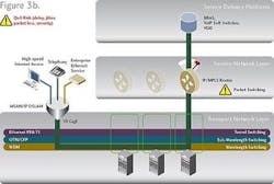
In our simple network diagram above, the risk of QoS issues exists at every Layer 2 switching hop in the transport network layer (four in all).
In the above discussion, we have identified two issues: first, QoS risk of packet switching, both with Layer 2 switching in the transport layer and Layer 3 switching in the MPLS service layer; and second, "tromboning" through inefficient planning and coordination of traffic through the network.
So how does the CET concept of service mapping address this problem?
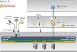
Very simply, CET offers circuit switching and transport technologies in addition to Layer 2 packet switching technologies to enable "service mapping" of traffic. This avoids the QoS risk of Layer 2 switching and enables Layer 1 and Layer 0 "cut-through circuits" to avoid transit "tromboning" at both Layer 3 and Layer 2.
As shown above, a CET system contains a switching fabric that, in addition to Layer 2 PBB-TE tunnel switching, includes Layer 1 OTN/ GFP aggregation and switching based on Time Slot Interchange (TSI) technology; and Layer 0 WDM wavelength switching, either multidegree wavelength-selective switch (WSS)-based ROADM technology and/or multidegree OEO crosspoint switching.
These technologies are not packet switched; streams of traffic are mapped from an input port to an output port without the inspection of a packet header by a packet switching processor. Thus, none of the potential packet switching QoS issues described above can occur.
In effect, a Layer 1 or Layer 0 "cut-through" circuit is established end to end, creating the same positive effects on Layer 2 switching as Layer 2 switching has on the MPLS layer. This technique reduces the amount of transit traffic that may be needlessly processed at Layer 2, allowing smaller Layer 2 switching fabrics to be used, and reduces the number of packet switching hops end-to-end for improved QoS.
However, it is very important to recognize that the CET architecture does not change the use of PBB-TE as the client interface protocol for all traffic. The compelling economics and simplicity of an all-Ethernet transport network are maintained. What is different is the fact that CET enables selective use of transport and switching technology on a tunnel-by-tunnel basis, i.e., service mapping. Some service providers may even find it useful to implement a CET network using regular Ethernet or other interfaces to these additional layers.
The business case for CET is broad. It is more deterministic, thereby lowering QoS risk. It enables a reduction in MPLS costs, and it facilitates further capital expenditure (capex) reductions through offloading Layer 2 switching. It may come as a surprise that the technology cost of the same capacity of Layer 2 switching is actually higher than an OTN/GFP-based Layer 1 switching fabric, which, in turn, is higher than a simple Layer 0 OEO crosspoint switch for WDM wavelength switching. CET does not change the total amount of switching capacity required at a transport node, but rather shifts some of it to less costly OTN/GFP and/or wavelength switching. Thus, the TCO of CET systems with hybrid fabrics is actually less—not more—than an Ethernet transport network based on Layer 2 switching alone.
In summary, connection-oriented Ethernet through PBB-TE offers many benefits as a common client interface to a CET network. However, the CET service mapping concept provides the following advantages over Ethernet transport networks that use Layer 2 switching only: It is more deterministic, thereby lowering the QoS risk for more traffic; it provides greater security for traffic types that require it; and it lowers the service providers' TCO.
Does connection-oriented Ethernet replace the MPLS network?
The short answer is no. Specifically, the CET architecture focuses MPLS where it shines and removes it from where it is overkill.
Carriers are turning toward Ethernet-based transport networks and away from pure IP/MPLS-based networks in part because of the difficulties they have encountered in using MPLS to solve all their transport network requirements.
A key concept in CET is the separation of the transport layer and service layer. It recognizes that MPLS is the traffic engineering technology of choice for the IP service layer and supports its use for that crucial element of end-to-end service delivery. However, the point of the CET architecture is to remove IP/MPLS from transport network functions that it was never designed for and instead use Ethernet, PBB-TE, and service mapping in the transport network to achieve lowest TCO, SONET/SDH-like QoS with sub-50 msec protection switching, and optimal security.
The separation of the service layer and the transport layer as a concept dates back 30 years to the late 1970s, when the mixing of networking and application processing was stifling the ability to scale industrial-sized IT applications. This led to the emergence of the seven-layer Open Systems Interconnect (OSI) model in 1984, a model that served both the carrier and IT communities well through the emergence of IP and the Internet as the world's ultimate multiservice, multipurpose network.
However, in recent years, the telecom industry has lost sight of some of the important concepts in separation of networking layers. In particular, carriers have attempted to force fit IP/MPLS as a "one size fits all" answer for all transport network applications.
The mixing of service layer and transport layer through the use of IP/MPLS (in some cases over WDM) provides the advantage of a single common technology for virtually all service and transport applications. However, larger carriers have determined fairly quickly that this architecture is too expensive and too complex to push to the edge of their networks and does not provide them with the flexibility they require to support all service types.
Smaller carriers were initially satisfied with a universal IP/MPLS approach, but they have also begun to search for alternatives in their access networks. Unfortunately, while MPLS is clearly the right option at the IP service layer, IP/MPLS directly over WDM or with an Ethernet overlay has not proved to be a success for the different needs of the transport layer versus the service layer.
In 2007, it has become clear to many of the world's largest carriers that, although IP/MPLS is without doubt the technology for applications at the service layer, it is not the right answer for all transport layer demands.
What are the management and control plane options for Ethernet transport networks?
As the discussion of our first two questions makes clear, CET networks are about more than Ethernet and PBB-TE; Layer 1 OTN/GFP transport and switching and Layer 0 WDM multidegree wavelength switching (via WSS ROADMs and/or reconfigurable OEO) both have key roles to play in the CET network.
For a truly successful CET network, OSS systems need a comprehensive, holistic approach to planning, provisioning, troubleshooting, and optimizing all of these layers as well.
Simply put, it is not enough to manage Layer 2 in isolation. Planning and provisioning decisions made for Layer 2 independently of Layer 1 and Layer 0 may result in diminishing the key benefits of CET—lowering QoS risk and reducing TCO—as described earlier in this discussion.
As service providers and vendors re-evaluate their transport networks and how to manage them, a few things are becoming clear. Emerging XML-based service oriented architectures for OSS offer many advantages over older architectures, especially home-grown ones. Furthermore, the availability of Ethernet path computation modules for Layer 2 and Layer 1 are crucial. There are applications for both in-network and offline systems in these areas. And generalized MPLS (GMPLS) and GMPLS-Ethernet label switching (GELS) do not appear to be equipped with all of the elements required to achieve these goals.
There are many intriguing questions raised by the migration to CET networks. And as the technologies mature and the industry gains more experience from real service provider deployments, we are sure to learn more.
Brian Prattis director of solutions marketing at Meriton Networks (www.meriton.com) and can be reached at [email protected]. He recently relocated to Meriton's corporate headquarters in Ottawa, Ontario, Canada, after spending the last few years living and working in the U.K. in Meriton's EMEA organization.
