The growing enthusiasm for Ethernet-based services shows no signs of abating. Indeed, the advent of 10-Gbit Ethernet (10-GbE)-with its increased bandwidth and improved fault-detection schemes-is accelerating the trend toward introducing Ethernet technology on core transport networks.
For a start, enterprise customers with an Ethernet infrastructure are upgrading their core transmission links to a 10-GbE local-area network (LAN) to leverage their existing infrastructure without losing functionality. Service providers are also migrating from a SDH/SONET-based infrastructure toward 10-GbE wide-area network (WAN) technology, enabling them to offer real-time applications such as video over IP and voice over IP (VoIP) without having to upgrade their entire network.
However, 10-GbE on its own does not guarantee the same level of performance as would be expected from a SDH/SONET network. Network operators must therefore test a number of network parameters to ensure that a deployed 10-GbE system delivers an acceptable quality of service (QoS) and to show customers that the network complies with the performance metrics specified in their service-level agreements (SLAs).
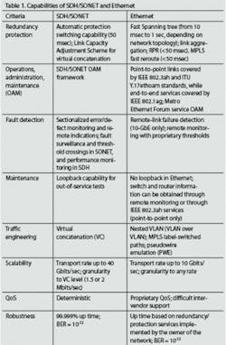
First of all, it is important to understand the key differences between the capabilities of SDH/SONET and Ethernet (see Table 1). These stem from the fact that SDH/SONET was originally created to transmit circuit-based voice traffic, while Ethernet was designed to carry packet-based data. Although SDH/SONET has since been modified to support data traffic more efficiently, it still lacks the flexibility inherent to the datacom world.
In contrast, the latest incarnation of Ethernet offers enough bandwidth to meet the requirements of today’s core networks, but in its most basic form 10-GbE lacks the high-level performance enabled by SDH/SONET. Ethernet on its own provides no protection mechanisms, no end-to-end service monitoring, and no default QoS, all of which come as standard in a SDH/SONET network.
While extra features can be added to improve performance, each one must be implemented and maintained by the network operator. As a consequence, the choice between SDH/SONET and 10-GbE largely depends on the type of traffic to be carried by the network. For example, a pure 10-GbE network might drive down the equipment cost but could incur higher operational costs because of the need to support extra protocols that guarantee the required performance.The need for additional protocols also makes it essential to perform network tests during installation and commissioning to ensure that a deployed Ethernet network provides the required level of service. In particular, these tests should ensure that the network is able to recuperate from network problems such as a protection switch, a link down, or inefficient traffic management.
In SDH/SONET systems exploiting some form of wavelength-division multiplexing (XWDM), the maximum threshold for chromatic dispersion for STM-64/OC-192 is around 1,176 psec/nm. On standard G.652 fibers, with chromatic dispersion typically less than 19 psec/nm-km in the C-band (1,530 to 1,565 nm), this means that regeneration or compensation sites must be spaced at intervals of around 60 to 80 km.
In contrast, the IEEE 802.3ae standard for 10-GbE transmission systems places a maximum tolerance on chromatic dispersion of 738 psec/nm -significantly lower than for SDH/SONET because 10-GbE networks exploit lower-performance lasers to save costs. A 10-GbE system based on the same G.652 fibers would therefore require regeneration or compensation sites every 40 km.
What’s more, the maximum tolerance of 738 psec/nm is based on a laser emitting at a constant 1,550 nm. But the acceptable wavelengths for a 10-GbE network span the entire C-band, leading to variable amounts of chromatic dispersion. In the worse case scenario, a laser operating at 1,565 nm would lower the tolerance even further and the maximum reach between compensation sites could be less than 40 km-and would need to be checked with a bit-error-rate (BER) test.
The same attention needs to be paid to PMD. The 10-GbE standard indicates that fiber with PMD of less than 5 psec at 1,550 nm is needed to provide the tolerance levels required by large corporate users-which could be hard to find, particularly with older fiber plant. In contrast, SDH/SONET requires PMD values of 32 psec at 2.5 Gbits/sec and 8 psec at 10 Gbits/sec to achieve the same tolerance levels.
Optical issues must also be addressed. For example, many network operators might be tempted to scale up an oversubscribed Gigabit Ethernet (GbE) link by simply replacing the end-point equipment with 10-GbE versions. This will have no impact on the data processing layer, since all the Ethernet frames will be processed and switched normally, but different optical specifications apply to 10-GbE networks. Most notably, the receiver sensitivity of 10-GbE optics with (short-reach) multimode fiber is much lower than for the optics used in GbE, which significantly reduces the operating range (see Table 2).
This means that a network operator would need to switch to singlemode fiber to provide 10-GbE operating ranges of more than 300 m. With 10-µm singlemode fiber, the operating range offered by 10-GbE networks is increased to 10 km, which is double the distance for a GbE signal over the same fiber.
Besides these physical and optical issues, traffic engineering must also be carefully considered when migrating to 10-GbE systems. Particular problems can arise at the interface between a LAN and WAN; two important factors to consider are the difference in transmission frequency tolerance and the difference in bandwidth.
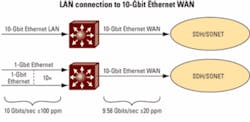
For a start, SDH/SONET networks are based on a master clock that is distributed to all network nodes, while Ethernet networks don’t have a distributed clock and have a much lower clock tolerance. When these two worlds are connected, the clock difference can be up to ±120 ppm in a LAN/WAN configuration (Figure 1) or even up to ±200 ppm in LAN/LAN systems, causing Ethernet frame loss when traffic is sent at maximum throughput.
Also, a 10-GbE WAN can only transmit an effective data rate of 9.58464 Gbits/sec. If the LAN network throughput is close to 10 Gbits/sec, Ethernet frames could be dropped at a rate of up to 415.36 Mbits/sec. Although a network operator could limit the ingress rate to 9.58464 Gbits/sec to address this problem, the difference in clock tolerance could induce an additional rate mismatch of 1.2 Mbits/sec. An RFC 2544 throughput test (as discussed later) should therefore be used to determine the maximum throughput that a 10-GbE WAN link can sustain.Another important traffic engineering issue is the use of “pause packet”-a flow-control protocol defined by IEEE 802.3x to backhaul the ingress traffic on point-to-point links when the internal buffers are close to saturation. When a threshold in the buffer set by the network operator is crossed, this scheme sends a pause packet to the downstream network element to stop the transmission of traffic until the local buffers are empty.
This pause threshold must be set at the right level to maximize throughput without losing any frames, and the effect of the pause frame is largely determined by the time taken for it to be transmitted and received at the downstream end. On fiber, one bit takes about 53 µsec to travel a 10-km span. In this time, a maximum of 79 frames can be sent on a GbE link, while a 10-GbE link is capable of transmitting about 788 frames. By the time a pause frame is sent and the traffic stopped, a 10-GbE link will receive 10 times more frames than a GbE link.
If the pause threshold is set too high, the reaction time will be too slow and the local buffers will overflow, causing frames to be lost. If too low, the pause frames will be sent too often, reducing the overall throughput and increasing packet jitter. Network operators should therefore exploit an RFC 2544 frame-loss test to determine the best threshold value.
Testing networks during installation and commissioning provides operators with a valuable record of network performance. These tests also form the basis of SLAs defined by telecoms operators and their customers to stipulate the expected QoS. The parameters used to define SLAs are typically network and application uptime/downtime and availability, mean time to repair, performance availability, transmission delay, link burstability, and service integrity.
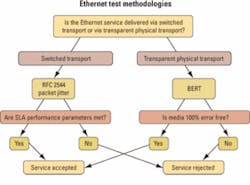
Test equipment is essential for a service provider to quantify most of these parameters. But certain tests are more important than others, depending on the type of network being tested. In a core network, for example, the bandwidth is usually delivered on a transparent physical network, and the test methodology is quite different to that required in a switched network where there is “processing” of Ethernet frames (see Figure 2).
For example, next-generation XWDM networks carry 10-GbE in a transparent way, while some service providers are also using 10-GbE to provide point-to-point wavelength services. Since these new services are totally transparent, service providers need a quick way to certify them and to provide parameters that can be used for SLAs.
This can be achieved with a BER-type test that measures a pseudo-random bit sequence inside an Ethernet frame. Such a test allows telecom professionals to compare results as if the tested circuit were SDH/SONET, not 10-GbE. Most telecom engineers are more comfortable with terms like BER and Mbits/sec, as opposed to packet loss rate and packets/sec, and this methodology provides the accuracy in bit-per-bit error count needed for the acceptance testing of physical transport systems.
If the network to be tested is switch-based-and so includes overhead processing and error verification-the BER approach is not the best one. This is because a network processing element will discard frames or packets if an error is found, which means that most errors will never reach the test equipment. These lost frames are more difficult to translate into a BER value.The other means to test a network on installation or when commissioning a customer circuit is to use RFC 2544 (benchmarking methodology for network interconnect devices). RFC 2544 test procedures incorporate four major tests-covering throughput, back-to-back (also known as burstability), frame loss and latency-to evaluate the performance criteria defined in SLAs. The results are presented in a way that provides the user with directly comparable data on device and network performance, and also allows a service provider to demonstrate that the delivered network complies with the SLAs defined in the contract.
First, the throughput test determines the maximum rate at which the device or network can operate without dropping any of the transmitted frames, providing a clear indication of the capability of a network to forward traffic under heavy load. The test also puts the network elements under stress when processing the different checks required at different protocol levels. Changing the frame size also puts extra stress on the network processing capability.
Second, the back-to-back value is the number of frames in the longest burst that the network or device can handle without losing any frames. This measurement is used to evaluate the network’s capability to handle short-to-medium bursts of traffic from an idle state.
Third, the frame-loss measurement is the percentage of frames that is not forwarded by a network device under steady-state (constant) loads due to lack of resources. This measurement can be used to evaluate the performance of a network device in an overloaded state, which is a useful indication of how a device or network would perform under pathological network conditions such as broadcast storms.
Finally, the latency test measures the time taken for a frame to cross a network or device-either in one direction or round-trip, depending on the availability of clock synchronization. Any variability in latency can be a problem for protocols like VoIP, where a variable or long latency can degrade the voice quality.
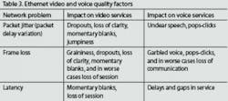
As service providers introduce new real-time Ethernet-based services such as video over IP and VoIP, they need quantitative measures of network behavior that can affect the service quality. Latency and frame loss can have a significant impact on these real-time applications, as can significant variations in the packet delay over time, also known as packet jitter (see Table 3).
Packet jitter is usually caused by queuing and routing across a network or buffering in switched transport networks. Although the variation in packet delay should be minimal in a core 10-GbE network, jitter can be introduced as bandwidth demand increases and more buffering occurs.
Packet jitter should not occur in core networks at low utilization rates. Tests for packet jitter should therefore be performed under heavy load to provide enough information for the service provider to fully understand the behavior of the network and foresee any QoS issues at maximum utilization. The maximum acceptable level of packet jitter is 30 msec for video applications and 10 to 20 msec for VoIP.
Since packet delay variation can result from queuing and buffering, it is important to measure jitter with test traffic that simulates a real application. Service providers must also ensure that the configuration of virtual LANs (VLANs) and other customer-defined services reflect typical end-user parameters. These measures will guarantee that the test traffic is processed in the same way as the customer traffic and that the measurements can be used to determine the buffer level required to absorb packet jitter, and/or to define SLAs.
There is no doubt that 10-GbE offers a more flexible alternative to SDH/SONET, and can achieve the same reliability if extra protocols are added to the basic technology. However, a number of network parameters must be verified to ensure that a 10-GbE WAN provides an acceptable level of quality. Test equipment can provide all the data needed to quantify network behavior, ranging from dispersion measurement of the fiber plant to network performance testing with RFC 2544 and packet delay variation.
These data are essential for service providers to prove that they are meeting their SLAs, and so prevent potential loss in revenue. But test equipment can also be used in a proactive way to monitor the behavior and performance of a network. This can enable early detection of any degradation in performance that could ultimately lead to a network outage, which in turn will improve network availability and help to achieve the figures set down in the SLAs.André Leroux is a datacom systems engineer (contact [email protected]) and Bruno Giguère is a member of technical staff at EXFO (www.exfo.com). This article first appeared in the April 2006 issue of FibreSystems Europe in Association with Lightwave Europe, page 14.


