Time-domain pulse shaping for increased spectral efficiency
The Swedish engineer Harry Nyquist explained in the 1920s that for eliminating ISI, the impulse response h(t) needs to fulfill the following requirement in the time domain:
for all integers n. TS is the pulse spacing of adjacent pulses.
In Figure 1, a signal that meets this condition – sinc (t) pulses – illustrates the impact of the criterion: The pulses overlap, but only the sampled symbol contributes to the response at the sampling instant tk. The other symbols are zero at this point in time. In this way, we have avoided the signal-degrading and error-inducing effects of ISI.
The right side of Figure 1 shows the Fourier transform (FT) of the impulse response. You can see that the frequency response that fits into a rectangular frequency window fulfills the Nyquist ISI criterion:
This means that the harmonics - the components with a frequency that is an integer multiple of the so called Nyquist frequency FS - must add up to a constant value, in order to fit into a frequency band without ISI. The Nyquist frequency FS is the minimum bandwidth needed to encode a signal without loss of information.
Nyquist pulse shaping using a finite impulse response filter
A sinc-signal may be perfect for preventing ISI as described above, but it is not practical because it is infinitely extended in time. Therefore we need to truncate it in the time domain, which is performed in practice by using a finite impulse response (FIR) filter. An FIR filter of order R responds for R+1 sample points and then returns to zero. Only past sample points x[n-i] are considered for the convolution of the filter output y[n] so that filtering can be performed in real-time.
The discrete-time FIR filter output y[n] in dependence of the input x[n] is described by:
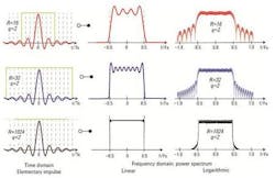
domain waveform, after Fast Fourier transformation power spectrum on
linear and on logarithmic scale. [2]
In the first line, with a filter order of 16, the signal spans 8 TS. In the FFT, we can see distortions caused by the limited time window. Most of the power lies within the Nyquist band (-0.5 FS to 0.5 FS) but a part lies outside the band. The power spectrum shows the harmonics as image spectra.
If we double the length of the filter (R=32), the signal better fits into the bandwidth, but we still see some ringing. At R=1024, the spectrum looks almost ideal; the ringing is only visible at the steep edges and the power spectrum also shows less out-of-band contribution. Unfortunately, the higher the order R of the filter, the higher the complexity of the filter design too. Therefore, you would usually stay with the lowest R that answers the requirements.
Raised cosine filters
For even better out-of-band suppression and a spectrum without ringing, raised cosine filters provide a reasonable alternative. Here, the impulse response is dependent on the so-called roll-off factor α which can take any value from 0 to 1:
domain presentation. [2]
In the frequency response, it stands out that for any value of α, the curves are crossing the same point at ±FS/2 , which is half the pulse rate. As mentioned before, this is the Nyquist frequency, the minimum bandwidth needed for a data transfer without loss of information. Apart from that, you can see that for α = 1, we hardly have any ringing but the frequency spectrum does not fit into the bandwidth. For α = 0, it is vice versa: the frequency response is rectangular within the bandwidth (the overshoots at the edges are a mere mathematical effect, also known as the Gibbs Phenomenon, and do not have any practical impact). The time domain signal now shows more ringing, though.
Why should we care about the ringing when we first stated that at the sampling point only the sampled symbol contributes to the signal? In practice, ringing is a problem because the other symbols have zero contribution when sampling only at this ideal instant. Under real world conditions, it is almost impossible to have the receiver sample exactly at this point in time so that we’ll always have some ISI that induces errors in the interpretation of the signal.
So, we obviously have a tradeoff between bandwidth containment and suppression of ringing in the time domain. A compromise in the choice of an adequate value of α has to be found on an individual basis for every fiber-optical application.
Raised cosine filters in practice
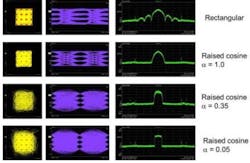
Let’s have a closer look at the influence of different roll-off factors on the most promising modulation scheme for 400 Gbps and higher data rates: 16-QAM. Figure 4 shows measurements not only of the frequency domain response but also the eye diagrams and the impact on the transitions between constellation points and the constellation points themselves.
factor α: constellation diagram, eye diagram and frequency spectrum; signals
created with an Agilent M8190A Arbitrary Waveform Generator.
The top example shows the case of non-shaped rectangular pulses. As we know, a signal that only occupies a fixed time interval has an infinitely extended frequency spectrum; we can see in the frequency response large side slopes. The eye diagram shows the typical behavior of a wide-band signal with open eyes. Between the constellation points, we have straight transitions.
Using a raised cosine filter with a roll-off factor α = 1, the frequency spectrum becomes narrower; the side slopes are not visible anymore. The eye diagram shows wide-open eyes. The constellation points are smaller. This is typical for a system with reduced bandwidth. The detection bandwidth on the receiver side is, by implication, also reduced, which lowers noise.
At a roll-off factor α = 0.35, the frequency width has further decreased, and with it the size of the constellation points. The transitions between the constellation points start to show much overshoot. This is because when reducing bandwidth the transitions between the symbols get extended in time, which is reflected in the constellation diagram by the long curved transitions between the points. The eyes are closing and therefore the sampling timing gets more critical.
An almost perfect rectangular spectrum is reached at α = 0.05. The transitions between the little constellation points show large overshoot. The completely closed eyes indicate that for avoiding errors, the sampling point has to be adjusted precisely.
How much spectral efficiency do we gain?
To get an idea of the quantitative gain in spectral efficiency by pulse-shaping filters, let’s compare it to the effects reached by applying orthogonal frequency-division multiplexing (OFDM).
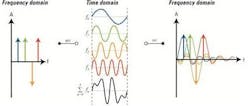
Figure 5 gives a brief recap of the OFDM principles, which are similar to the Nyquist format.
In OFDM, the frequency sub-spectra are sinc-shaped. For increased spectral efficiency, they are overlapping but because of their orthogonality – meaning that they are shifted by multiples of π/2 – they do not interfere with one another. In the time domain, a symbol is a sum of sine curves with equidistant carrier frequencies fn in a fixed time window. In this example, we have in one channel four subcarriers at four frequencies. The orange is phase shifted by π, as can be seen after inverse Fast Fourier transformation (IFFT).
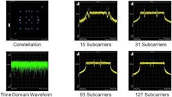
Figure 6 now shows spectral analysis on a measured 16-QAM modulated OFDM signal.
subcarriers; signals created with an Agilent M8190A Arbitrary Waveform Generator.
On the top left side, you can see the constellation diagram and below the time domain waveform. With 15 subcarriers and two pilots, we get a fairly flat frequency spectrum and a steep roll-off.
By increasing the number of subcarriers, the spectrum is flattening and the two pilots are moving towards the center. At the bottom line, we see that the spectrum is approaching rectangular shape with the growing number of subcarriers.
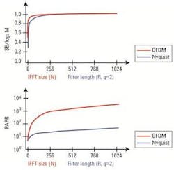
How does this translate now into a gain of spectral efficiency in comparison to that reached by Nyquist pulse shaping? For the sake of comparability, in Figure 7, the normalized spectral efficiency (SE) is plotted over the Nyquist filter length R (the oversampling factor q is chosen again to be 2) versus the number of OFDM subcarriers N.
spectral efficiency and peak- to-average power ratio (PAPR) [2].
The figure shows that both techniques provide almost the same result regarding spectral efficiency.
The comparison of the also normalized peak-to-average power ratios (PAPR) reveals similar behavior at differing levels. The PAPR of OFDM time domain waveforms is much larger. This phenomenon owes to the fact that in In OFDM, the signal exhibits some peak values high above the average power level. As a consequence, OFDM circuits and test instruments need a large dynamic range to avoid distortions induced by clipping the higher levels. For optimized spectral efficiency, pulse shaping can be applied in combination with OFDM.
Up to this point, we have touched on the technical requirements for the more sophisticated data transmission concepts several times. In the next article of this series, we’ll investigate in detail the challenges imposed by complex modulation for the technical implementation of an optical transmitter.
Figures: Dr. Bernd Nebendahl, René Schmogrow
References
- H. Nyquist: Certain Topics in Telegraph Transmission Theory, Trans. AIEE, Vol. 47, pp. 617-644, Apr. 1928
- R. Schmogrow M. Winter, M. Meyer, D. Hillerkuss, S. Wolf, B. Baeuerle, A. Ludwig, B. Nebendahl, S. Ben-Ezra, J. Meyer, M. Dreschmann, M. Huebner, J. Becker, C. Koos, W. Freude, and J. Leuthold,: Real-Time Nyquist Pulse Generation Beyond 100 Gbit/s and its Relation to OFDM, Optics Express, Vol. 20 (1), pp. 317 – 337, Jan. 2012
Stephanie Michel is technical marketing engineer in the Digital Photonic Test Division of the Electronic Measurements Group at Agilent Technologies.


