A new generation of optical-component technologies promises faster and more dynamic lightwave networks. Chromatic and polarization-mode dispersion compensators will become key elements in networks with long reach at high bit rates. Filters that tune precisely over both wavelength and amplitude will be at the heart of a new generation of remotely configurable metro core networks. And advances in fabrication techniques are moving passive components onto chips where they will be integrated with other network elements.
All of these component technologies will create a test and measurement challenge to their manufacturers. Because today's new DWDM components are designed to operate precisely over narrow channel spacing on tight loss and dispersion budgets, they must be carefully and accurately measured over a growing number of parameters at increasingly narrower resolution.
Measurement instrumentation therefore must keep up with the demands of such advancing component technologies. There are basically five key elements to optical-component test (OCT): speed, accuracy/resolution, scalability, usability, and cost. Optical vector analysis offers a means to integrate these elements in one fast, accurate, easy-to-use platform. The resultant optical test instrumentation not only can help component manufacturers save time and money, but it also can enable the development and production of technologies that help vendors differentiate their products.
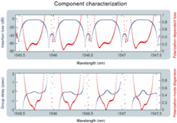
The requirements for complete component testing vary according to the application and environment. Generally speaking, full component characterization requires measurement of a component's amplitude, phase, and polarization response as a function of frequency. For DWDM networks—high-bit-rate networks that support many narrowly spaced channels—all three parameters are crucial.Amplitude effects are characterized by measuring insertion loss (IL) and return loss (RL); phase effects are characterized by measured group delay (GD), which is sometimes referred to by its mathematical derivative: chromatic dispersion (CD). IL and GD are polarization-averaged parameters. That is, they represent the response of the component averaged over all incident polarization states. Polarization effects are characterized by measuring polarization-dependent loss (PDL) and polarization-mode dispersion (PMD). So we arrive at the standard set of four parameters that characterizes optical components: IL, PDL, GD, and PMD. Figure 1 displays these four parameters over four channels of a 40-channel DWDM optical interleaver.
This list is not complete; with the introduction of even higher-bit-rate systems (40 Gbits/sec) looming, the list will likely grow. That is due mostly to the fact that the phase parameters can be thought of as "first order" approximations of how components affect traffic. For higher-bit-rate systems, higher-order effects begin to become important, and components will likely need to be further characterized by parameters like second-order PMD (SOPMD).
For components designed to operate in the C- and/or L-bands, the above parameters need to be measured over a wavelength range of about 100 nm from 1520 to 1620 nm The required resolution is dictated by the data rate and channel spacing; it is usually on the order of a few picometers, with the required wavelength accuracy better than a few picometers.
There are also very specific requirements placed on the accuracy and dynamic range required to measure each parameter. Designers generally want to be able to spec their components for loss with a precision better than ±0.1 dB over a dynamic range of 60 dB. That requires loss measurements with accuracy better than ±0.05 dB and often as low as ±0.01 dB. Delay measurements are becoming even more difficult, with many manufacturers requiring accuracies on the order of tens of femtoseconds for both GD and differential GD at resolutions of 10 pm.
Therefore, challenges lie in performing complete OCT on the types of modern components that require complete spectral loss and dispersion characterization and have multiple input and output ports, are tunable, or require precise optical alignment to function properly. This complexity has the potential to amount to millions of data points and hours of testing per component and a major headache for the manufacturer.
The traditional approach to OCT has been to use separate test stations for each measurement. Given the number of parameters and level of complexity required to accomplish rigorous component test, this approach has become undesirable. It is not only expensive since it requires redundancy, but also connecting and disconnecting components to multiple instruments is far too slow and tedious. In fact, meeting both cost and speed-of-test requirements using standalone instrumentation has become nearly impossible.
That has led instrument manufacturers to integrate the various systems and subsystems required to perform rigorous OCT into a single platform. Generally, those elements include a tunable-laser source, a wavemeter, a polarization controller, a modulator (for phase measurements), and optical receivers.
Integrating these elements into a single test stand eliminates the connect/reconnect issues associated with testing at multiple stations. However, it does not eliminate the need for multiple measurements to cover all the required tests. That's because the method used to measure PDL, for instance, is different from and requires different hardware than the method used to measure CD. The result still is multiple tests per device, meaning slower tests and bulky and often expensive and difficult-to-use test equipment.
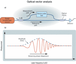
Optical vector analysis is a measurement method based on coherent interferometry that results in a totally integrated all-parameter test station capable of meeting the stringent needs of modern DWDM components. The general idea behind optical vector analysis is to treat optical components and modules as four-port devices: two polarization modes in and two polarization modes out. The motivation for that is the two-fold polarization degeneracy in the singlemode fiber to which most components are connected. Hence, a singlemode device is described by four complex parameters—or transfer functions—that relate the coupling of the input modes to the output modes. These parameters can be compiled into a 2×2 matrix that, when measured as a function of wavelength, completely characterizes the device under test (DUT). From this matrix, all the linear parameters of interest (IL, PDL, GD, PMD, etc.) can be calculated.The matrix elements that describe the behavior of the DUT are measured using coherent interferometry, which is sometimes referred to as swept-homodyne interferometry. The basis for the coherent interferometric measurement method is the optical mixing of signals to obtain amplitude and phase information about a DUT. The basic idea is as follows: Light from a mode-hop-free tunable-laser source is split into measurement and reference paths of optical fiber. The measurement path includes the DUT, and the reference path comprises a fixed length of singlemode fiber. Once the light on the measurement path runs through the DUT, the two paths are recombined using a coupler and sent to an optical receiver. A simplified version of a coherent interferometer is shown in Figure 2. Interferometric fringes that can be related to the amplitude and phase response of the DUT are recorded as a function of laser frequency. From the amplitude and phase response, IL and GD information can be calculated. Hence, from a single measurement, loss and dispersion are obtained.
Polarization effects (PDL, PMD, etc.) can also be obtained in a single scan by conditioning the optical signal in the fiber before it propagates through the DUT. That is accomplished interferometrically by multiplexing different polarization states with slightly different delays upstream of the DUT. Combined with a polarization-sensitive receiver, this technique yields single-scan measurements of all four complex transfer functions that describe a component.
This approach represents a major departure from the traditional approach to all-parameter analysis. Among the major benefits of interferometric methods are:
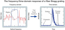
Figure 3 shows the frequency and time domain response of a fiber Bragg grating. Errors in the connection and fabrication process may be evident but difficult to distinguish in the frequency domain, yet are clearly visible in the time domain.
Another more subtle benefit of the coherent interferometric approach to OCT is the manner in which the data is collected. The optical-matrix representation is notationally compact, making data easy to store, recall, and reanalyze at a later date. Since the matrix characterization contains all the linear parameters of interest, it is extremely useful for computational modeling. For instance, designers often are interested in using measured data for a component to predict the performance of that component when it is dropped into a system. That can be accomplished by running eye-diagram and power-penalty simulations. The problem is it is difficult to assemble columns of measured parametric data (IL, PDL, etc.) for a given component into a meaningful prediction of an optical eye-diagram. The matrix characterization intrinsic in coherent interferometry leads transparently to an eye-diagram simulation through a simple frequency domain multiplication of the simulated information-carrying optical signal and the measured matrix response of the DUT. In this manner, all the deleterious effects of a component are accounted for automatically.
The introduction of fast, widely tunable mode-hop-free lasers with "good" tuning characteristics has been the greatest enabler in the commercialization of the coherent interferometer for OCT. Still, optical vector analysis does have its limits, the most important of which is the limited measurement length. Interferometry relies on mixing two delayed optical signals and measuring a beat-note. The frequency is proportional to the laser tuning rate and the delay difference between the measurement and reference optical paths. For a fixed laser-tuning frequency, that puts an upper limit on the length of the measurement path. For currently available systems, this limit is on the order of 100 m. Hence, the coherent technique and optical vector analysis are limited to optical components and assemblies of <~100 m.
Environmental fluctuations like acoustic vibrations and temperature fluctuations can cause deleterious effects in interferometric measurement systems. Rapid laser tuning (100 nm/sec) and fast, high-resolution data acquisition (12-bit, 10-Msample/sec) systems help to minimize the effect acoustics can have on measured data. The speed of the technique also enables many data sets to be averaged, allowing for even greater mitigation of environmental effects. Current systems are being designed with precise temperate control and internal calibration routines that allow for system operation over normal fluctuations in room temperature (±5°C).
The passive network elements that form the backbone of lightwave transmission systems (multiplexing/demultiplexing, optical add/drop, optical crossconnect, etc.) require extensive testing to assure not only robustness, but also functionality. The need for multiple tests over increasing wavelength ranges, with narrow resolution, is forcing vendors to look at "all-in-one" test equipment that integrates the key element characterization requirements. Advances in tunable-laser technology and interferometric sensing systems have introduced coherent interferometry as a viable solution for integrated all-parameter characterization of optical components and modules. This new type of instrumentation is enabling next-generation component- and module-level technologies by integrating the test and measurement elements critical to bringing these technologies through development and into production in a cost-effective manner.
Dr. Brian J. Soller is a senior research engineer at Luna Technologies (Blacksburg, VA).


