Fiber Bragg gratings help WDM push limits of fiber capacity
Design, manufacture, packaging, and testing all play crucial roles in optimizing the spectral response of high-performance devices.
FRANÇOIS OUELLETTE, Kromafibre
The advent of wavelength-division-multiplexing (wdm) as the technology of choice for upgrading the capacity of fiber-optic networks has created a demand for devices and components capable of pushing that capacity to its limit. Fiber gratings are well suited for the challenge, due to their inherently narrowband--almost square--wavelength response function. Fiber gratings also find other uses in communications systems, for example, as gain equalizers, where their spectral profile is made to match the gain curve of an erbium-doped fiber amplifier. Linearly chirped gratings are also used as dispersion compensators.
Due in part to their growing utility in the wdm environment, fiber gratings have pervaded the marketplace and found numerous applications in telecommunications and optical-fiber sensors. These different applications all have their own requirements for appropriate design of grating spectral responses and other grating properties. In particular, the use of fiber gratings as narrowband filters in dense wavelength-division multiplexed fiber-optic communications systems imposes stringent specifications on parameters such as the spectral shape of the grating, its overall loss, and its polarization dependence. By combining design and simulation tools with advanced fiber- grating fabrication and packaging techniques, however, it is possible to meet those specifications with a high degree of precision.
Among the factors that affect device performance are design parameters such as spatial profile, apodization, and chirp; constraining factors in fabrication technology such as grating length and strength; use of reliable and environmentally stable packaging, and use of proper measurement techniques for grating characterization. With the above factors in mind, this article briefly describes the processes of grating design, manufacturing, packaging, and testing.
Grating design
A fiber Bragg grating consists of a periodic stack of regions of higher and lower refractive index along an optical fiber. It has the property of reflecting light within a narrow band of wavelengths and transmitting all wavelengths outside of that band. The central reflected wavelength is equal to twice the period of the grating, multiplied by the fiber refractive index. For example, a grating reflecting at 1560 nm would have a period of about 535 nm. Gratings are made by exposing the fiber to an interference pattern of ultraviolet (UV) light. The refractive index of the fiber is permanently raised by exposure to UV light, so the fringe pattern is transformed into a refractive index pattern.
Three parameters characterize a fiber Bragg grating: its strength, its period, and its length. The first two parameters can actually be made to vary along the grating. And it is by selecting the appropriate profiles for these two parameters that one can obtain custom-tailored spectral responses to suit different applications.
The length of fiber Bragg gratings--despite the fact that they have been made with lengths to 1 m--is constrained by the size of the fabrication system, which is normally limited to a few centimeters. This also limits how narrow a grating response can be, because the reflection bandwidth of an unchirped grating is inversely proportional to its length. For instance, a 1-cm-long grating would produce a spectral width of about 0.2 nm.
Grating strength is also limited. The limitation in this case is determined by how much UV-induced refractive index change is achievable in a given fiber. In a photosensitive fiber, the refractive index change can be as high as 2 ¥ 10-3, which is sufficient to give more than 99% reflectivity even for a 2-mm-long grating. The fiber can also be loaded with molecular hydrogen at very high pressure to increase dramatically its photosensitivity with achievable index changes to 10-2. The gain is counterbalanced, however, by larger photo-induced loss in the fiber and a more complex fabrication process.
The period of the grating can be varied by relatively large amounts along the grating with a linear or nonlinear chirp covering tens of nanometers. This allows for the fabrication of custom-tailored gain equalizers, for example.
Grating manufacture
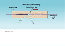
A popular technique for writing gratings involves "contact printing" through a phase mask (see Fig. 1). The phase mask is itself a grating, etched in a silica substrate, with an etching depth such that it diffracts most of the light in the +1 and -1 orders. Those two diffraction orders generate the interference pattern. In that technique, the fiber is placed directly behind the mask and exposed either to a beam having a width corresponding to the desired grating length or to a narrower beam that is translated back and forth along the mask.
The latter method is preferred because it makes the grating shape independent of the beam shape or width and actually allows the grating strength to be varied at will along the grating to generate a particular profile. The grating strength is usually controlled not by varying the UV intensity but by varying the fringe contrast. That way, the average index change, and thus the average refractive index of the fiber, remains constant along the grating. Because the grating period is directly proportional to the fiber average refractive index, it is important that the refractive index be constant to avoid introducing an artificial period variation (chirp) into the grating that would distort the spectral response.
One way to control the fringe contrast is to dither the phase mask at high frequency with a piezo actuator that has an amplitude up to one half period, which is sufficient to completely blur the interference fringes. A suitable control of the piezo modulation amplitude, synchronized with the scanning of the UV beam to write the grating, allows the fabrication of a grating with the desired strength profile.
Finally, the grating chirp can be implemented in the phase mask itself. However, any fabrication setup that relies on making a phase mask with a given design, while gaining in simplicity, loses a lot in flexibility. Also, the time lag between design and fabrication is greatly extended. At Kromafibre, we have developed a flexible, proprietary fabrication technique based on a computer-controlled interferometer rather than on a phase mask. The method allows us to change the period (by changing the angle of the interferometer mirrors) and the strength at will along the grating. Therefore, gratings of different wavelengths with arbitrary profiles and chirp can be developed much more quickly.
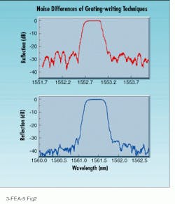
Any fabrication process will introduce imperfections in the grating that make its spectral response deviate from the theoretical one. Random noise in the grating profile, in particular, can degrade the grating response significantly. This is not as apparent in the central grating reflection peak as it is outside of that peak--a reflection "floor" appears that can change the bandwidth utilization factor of the grating and even make it practically unusable.
Figure 2 (top) illustrates the reflection spectrum of a grating with significant noise. The isolation between adjacent channels would be limited to -25 dB. That grating was written using the phase mask method, which has the disadvantage of reproducing all the noise in the mask in the grating. Figure 2 (bottom) shows a similar grating with much reduced noise, fabricated using Kromafibre`s proprietary interferometric technique, giving more than -35 dB of isolation. Such a low noise level can be achieved only by careful attention to every detail of the fabrication process.
Packaging
The packaging of fiber gratings must meet the same reliability requirements as other passive fiber components, such as fiber couplers. Bell Communications Research (Bellcore--Morristown, NJ) specifications are a good example of the requirements that component manufacturers specify.
Packaging can also be used to greatly reduce the temperature dependence of the central reflected wavelength of the grating to a level acceptable for wdm systems. Temperature-compensated packages have traditionally relied on the use of two materials with different expansion coefficients. The materials in these packages are carefully arranged such that the strain on the fiber actually reduces with temperature, compensating for the fiber expansion. These packages, however, have the disadvantage of requiring carefully machined, bulky parts. In addition, the total length of the package has to be longer than the grating itself to allow for the compensating members.
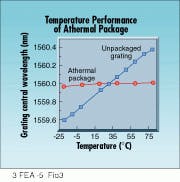
In an alternative approach, the fiber grating is fixed to a material with a negative expansion coefficient that is tailored to cancel the positive expansion of the fiber. The size and complexity of the package are much reduced, as is the cost, and the package can easily be scaled to longer gratings (see Fig. 3).
Measurement
Grating characterization must have a level of precision equivalent to the specifications. The use of optical spectrum analyzers with typical maximum resolution of 0.08 nm does not allow a precise measurement of the grating bandwidth and fine structure. The combination of tunable external-cavity diode lasers--with wavelength steps of 0.001 nm--and wavelength meters for accurate absolute measurement of the wavelength comprise the system of choice for proper characterization of grating response. The polarization- dependent loss and polarization-mode dispersion also need to be measured, as well as the group delay. A detailed description of how those measurements are made, however, falls outside the scope of this article.
Fiber Bragg gratings have come a long way since the first demonstrations by researchers from United Technologies (Hartford, CT) in 1989. They are now sophisticated components that are basic building blocks of many wdm systems. Their spectral response can be tailored to meet the stringent specifications of those systems. Special fiber designs reduce loss to cladding modes, while advanced packaging techniques reduce their temperature dependence. The advances in grating fabrication technology benefit applications such as gain equalization and dispersion compensation that are also an important part of wdm systems. u
François Ouellette is president of Kromafibre (Boucherville,QC, Canada), www.kromafibre.com.
This article is reprinted from the March 1998 issue of Laser Focus World, another PennWell publication.Fig. 3. The athermal package reduces the temperature dependence of the grating central reflected wavelength to less than 0.4 pm/°C compared with the wavelength dependence of an unpackaged grating (8 pm/°C).
Requirements for WDM filters
One application where a grating must meet stringent specifications is that of a filter for a wavelength-division multiplexing (wdm) communications system. Such a filter must ideally reflect all light over a given bandwidth--the bandwidth being typically a fraction of a nanometer--and transmit all other wavelengths. To make the most efficient use of the fiber capacity, the wavelength channels must be as close as possible, while avoiding crosstalk.
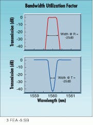
The ability of a filter to perform such tight filtering can be evaluated by the so-called "bandwidth utilization factor" (buf--see Fig. 1). This is defined as the ratio of the bandwidth at which more than a given fraction of the light is reflected (say 99.9%) to the bandwidth outside of which a similar fraction of the light is transmitted. An ideal filter would have a buf of 1. The actual value for a given filter depends on its design, but also on how well a given design can be implemented.
The requirements for a given wdm filter depend on the system specifications, such as the magnitude of crosstalk considered acceptable. Most systems require at least 25 dB of isolation between channels, and some require as much as 30 or even 35 dB. So in most cases the reflection from the grating must not be more than -25 dB outside of its reflection bandwidth. At the same time, the bandwidth over which light is reflected at more than 99.9% must be at least as large as the signal bandwidth. It must also include room for wavelength drift over time and tolerance for the emitter`s wavelength.
To achieve high reflection over a given bandwidth and minimize reflection outside of that bandwidth, the grating must have a smooth spatial profile, a typical example being a Gaussian profile. Figure 1 shows the reflection and transmission spectra of such a Gaussian-profile grating, the full width at half-maximum of the profile being 6 mm and the total length 16 mm.
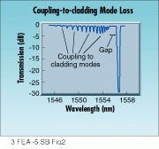
The loss outside of the grating reflection band is also an important factor. The grating reflects light guided by the core of the fiber back into the core, but it can also couple some of that light into cladding or radiation modes. Such coupling occurs on the short-wavelength side of the grating and introduces unwanted loss (see Fig. 2). There are two solutions to this problem. The fiber can be designed to minimize the coupling-to-cladding modes, for example by making both cladding and core photo sensitive. Or the fiber can be made to have a very high numerical aperture and a very well guided mode. In the latter case, the gap between the grating central reflected wavelength and the cladding-mode loss--which would typically be about 2 nm--is increased to as much as 10 nm or more. This is acceptable in applications where all system channels fall within the gap between the grating central reflected wavelength and the cladding mode loss.Fig. 2. At wavelengths shorter than the grating main reflection peak, additional resonances that correspond to light coupled into cladding modes appear in the transmission spectrum. The additional peaks do not appear in the reflection spectrum because the light is lost outside of the fiber core.
