AWG passive thermal compensation techniques for WDM-PON
by Jacques Bismuth, Martin Boulanger, and Jan Ingenhoff
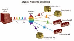
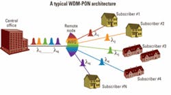
Fiber to the home (FTTH) is now receiving increased attention, as telecommunication carriers begin to upgrade services from traditional voice and/or broadband to full triple play. Market estimates show that in the very near future, the average bandwidth required by the subscribers will be up to 1 Gbit/sec. The shared PON architectures (B/E/GPON) currently used in access networks have issues in delivering this level of bandwidth. They also offer very limited upstream bandwidth. Thus, there is a consensus that next-generation PON systems will use WDM in WDM-PON architectures that offer large symmetric bandwidth (Fig. 1).
Because they are passive and have excellent optical performance, athermal arrayed waveguide gratings (AWGs) are the perfect candidates to perform the WDM function in such systems. Furthermore, they are based on the same planar lightwave circuit (PLC) platforms as the power splitters used in current access networks, so their pricing should become similar in volume.
The requirements for the AWG for WDM-PON are different than for normal metro applications. In WDM-PON architectures, the AWG at a remote node is located in the field. It can be anywhere in the world and deployed differently�in a telephone switch box on a sidewalk or in a manhole, for example. The remote node is prone to an uncontrolled environment and therefore may be subject to extreme temperature variations and flooding.
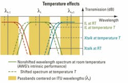
The main challenge is the temperature. Temperature affects some of the optical performance parameters that matter most to system vendors, i.e., the insertion loss (IL), the polarization-dependent loss (PDL), and the channel isolation (Xtalk). For each of the AWG�s channels, these parameters are specified over a given wavelength passband (PB), centered on the fixed standardized ITU grid. For 100-GHz channel spacing devices, the PB is typically ±100 pm.
Without compensation, AWGs are very sensitive to temperature. Variations of the temperature cause a shift of the AWG�s demultiplexed wavelength spectrum, initially aligned on the PB grid. So even though the AWG�s intrinsic optical performance is not directly affected by the temperature, it is affected when the optical parameters are measured across the fixed PB and the wavelength spectrum is shifted (Fig. 2).
The main reason for the AWG�s wavelength shift is the thermal dispersion of the optical layers constituting the PLC structure, i.e., the temperature dependency of their refractive index (dn/dT). For silica-based PLC technologies, the AWG�s wavelength-shift temperature dependency is typically 11 pm/°C. The wavelength shift is in fact a second-order polynomial function of the temperature and this is only the first order of the polynomial.Thus, the AWG thermal insensitivity techniques consist of passively stabilizing the AWG�s output spectrum when the temperature varies over a very large range, ideally as large as 120°C around room temperature (RT), typically from �40°C to +80°C.
Two main techniques are used by component vendors to passively accomplish the thermal compensation of the AWG wavelength shift. One technique works with the thermo-optical properties of the materials, and the other works on their thermo-mechanical properties.
When it is done optically, the technique consists of locally modifying the guiding structure by inserting special optical materials. The materials are designed such that their thermal dispersions (dn/dT) are opposite of the ones of the main guiding structure. In silica-on-silicon technology, this implies that the material must exhibit a negative thermal dispersion. The thermal dispersion also has to be large enough to be able to compensate, across a small length, the totality of the effect of the rest of the AWG.
When the compensation is done mechanically, the technique consists of fixing the AWG input at one end of an arm made out of metal or alloy, for example. The arm is attached to the PLC in such way that its thermal expansion causes a displacement of the AWG input along the input edge of the PLC. When the temperature changes, the arm elongates or contracts, moving the AWG input at a rate proportional to both the arm�s length and the arm�s coefficient of thermal expansion (CTE).Compensation occurs because moving the AWG input along the input plane has an effect similar to the one of the temperature; it causes a proportional shift of the transmitted wavelength spectrum. The compensation is then achieved by carefully calculating the length of the arm such that, as the temperature varies, the AWG input is moved to the position that causes a wavelength shift opposite to one caused by the AWG�s thermal sensitivity.
Optical compensation has the advantage of not involving mechanical movement, seen as a reliability issue due to the potential wearing out of the parts in motion. On the other hand, the special optical materials used in today�s products are sensitive to the environment and may be subject to aging. To protect them the device housing has to be hermetically sealed, which increases the component price.
Mechanical compensation systems obviously involve mechanical movement, but they do not require fully hermetic packaging. However, since the device is to be used in an uncontrolled environment, it still has to be reasonably well sealed�like a waterproof watch, enough to withstand total immersion in muddy water for a few days during the monsoon season in Asia, for example.
In terms of material selection and design, because they are used in many industries and for a long period of time, thermal modeling data of metals and alloys are numerous. This data helps to create reliable design performance estimates. This is not the case for data on materials used in optical compensation techniques; their availability is not as great.
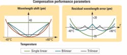
Compared to optical compensation, one benefit of the mechanical approach is that mechanical techniques exist that allow the division of the operational temperature range in multiple smaller sub-ranges. The techniques involve the addition of extra compensating arms, each one only compensating for the AWG�s wavelength shift over a given temperature sub-range. The sub-ranges being smaller, there is a better fit between the linear expansion of the arm and the quadratic shift of the AWG. The residual wavelength error, which measures the difference between the two effects, is reduced, and the thermal compensation is better (Fig. 3). A practical example of such a multi-arm compensation system, where the operational temperature range is divided in two sub-ranges, is presented in the next section.
Optical techniques do not offer this flexibility. The optical compensative materials have to perform adequately over the full specified temperature range of operation. Because the light travels along a same path in the AWG, whatever the temperature, even if it is possible to add different optical materials their influence will always be felt across the full extent of the temperature range.
Even though the deployment of WDM-PON systems is still at an early stage, several component vendors already propose athermal AWG products based on single and multi-mechanical compensation schemes. Some are already used in field trials.
In single compensation systems, the residual wavelength error is a quadratic function of the temperature. The thermal expansion of common materials being mainly linear, a single arm compensates only for the first order of the quadratic dependency of the AWG�s thermal wavelength shift. Although it depends on both the technology and on the specific AWG design, the typical residual wavelength error of such single compensation systems is about ±20 pm across a temperature range of 120°C (Fig. 3). Then, depending on the actual operational temperature range and the PB specifications of each product, this is translated, in different ways, into the optical performance parameters of the device (loss, PDL, and Xtalk).
Interestingly enough, the wavelength compensation for current optical systems seems to be similar to one of the single mechanical arm techniques.
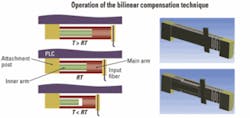
To improve the compensation, and the overall product performance, more arms can be added. However, adding arms also adds complexity to the design. The challenge is to develop multicompensation systems that are still easy to implement, do not have a big impact on the component size, and are still reliable. The added complexity has to be balanced with the gain in performance. As of today, it seems that a good balance is around two or three arms. Across the same 120°C temperature range, the residual wavelength error of a bilinear compensation system is typically ±7.5 pm, i.e., about 3� better than single compensation. For a trilinear system it is about ±5 pm, i.e., 4� better.One technique to achieve bilinear compensation is to insert a compensating arm within another one. Starting from a single compensating arm exhibiting a given CTE, a second one with a higher CTE is inserted through a hole made in the main arm (Fig. 4). Because of its higher CTE, the inner arm retracts in its hole when the temperature falls and has no effect; the displacement of the AWG�s input is only proportional to the length of the main compensating arm. On the other hand, when the temperature rises, the inner arm expands more than the hole in which it is fitted. It then acts like a piston, pushing on the main arm. At the end, the elongation of the main arm supporting the AWG�s input is larger than if the inner arm was absent.
The resulting elongation is in fact a combination of both the arms� thermal expansions and mechanical elasticity properties. Computer simulations are helpful tools in the design of these complex systems. The advantage of this approach is that it has almost no impact on the product size or on its reliability compared to the initial single compensation system; it just requires a few extra assembly steps.If the demand for higher access bandwidth keeps increasing, fully nonlinear systems that perfectly compensate for the AWG thermal shift might be needed in the future. Different mechanical approaches that may lead to perfect compensation are pursued. One of them would be to devise a practical and easy-to-implement way to mechanically transform the linear thermal expansion of an arm into a nonlinear movement. One can also think of playing with the materials� thermomechanical properties, by designing a special alloy or composite material with a CTE that varies adequately with the temperature.
Jacques Bismuth is senior optical design engineer, Martin Boulanger is senior waveguide design engineer, and Jan Ingenhoff is chief scientist officer at Ignis Photonyx (www.ignis.com).
