by Francis Audet, Gwennael Amice, and Stephane Chabot
The increasing deployment of reconfigurable optical add/drop multiplexers (ROADMs), the explosion of bandwidth (10 and 40 Gbits/sec), and market factors such as triple play have put tremendous pressure on existing networks — and with this added pressure comes added challenges.
Now more than ever, carriers need accurate measurement of chromatic dispersion (CD) and polarization-mode dispersion (PMD) on their fiber-optic links. Yet the expense involved in meeting this requirement often can exceed the amount set aside in the budget, making an affordable, efficient, and accurate method to test both CD and PMD a necessity.
During fiber characterization, optical time-domain reflectometers (OTDRs) are used to check end-to-end continuity, span loss, and splice and connector quality. However, the single-ended CD test instruments on the market are often inaccurate. Additionally, no single-ended PMD test instrument exists, which means CD and PMD qualification requires two technicians and two (or more) box setups. However, a new method for dispersion testing can provide a better alternative.
The OTDR method was introduced several years ago to measure CD through a single end of the fiber. For this method to work, the fiber far end needs to offer high reflection, which means that some intervention may be required; however, no special expertise or additional test boxes are required.
While sparing the second box required for highly accurate end-to-end measurement, the OTDR method has several well known flaws. The first is the amount of test points. CD is the rate of change of the delay as a function of a wavelength, which means that the best and most common way to calculate CD is by measuring the delay between a number of wavelengths, and then matching those points together according to a mathematical model (defined by IEC and ITU standards). Several fiber types, including G.652 and G.655 fibers, are modeled via the Five-Term Sellmeier equation; this five-term equation requires that five data points be known in order to obtain a good match. Obviously, a test method that only provides four test points (such as when using a four-lambda OTDR) cannot model this properly. The result is an improper match, which leads to errors in calculating the CD. For this reason, single-ended CD OTDR methods always give the same biased CD results — which, while repeatable, cannot pretend to be accurate or traceable to standards.
Second, if the network includes more than one fiber type, the total end-to-end CD cannot be modeled by a simple equation, such as the one just mentioned. The actual CD measurement derives from a mix of several differently fitting equations. The final outcome is thus more complex, and the limit of four points with a standard OTDR results in a measurement that is even farther from the truth in these cases.
However, many networks have longer links. In fact, for 10-Gbit/sec transmission, CD becomes an issue mainly at 80 km and longer distances. This factor indicates that when testing becomes essential, one of the test points is lost, which results in drawing even further from the model described earlier and risking additional loss in accuracy.
Fourth and finally, while the one-ended approach would appear to offer a "free OTDR," usability is limited because the laser must be a distributed feedback (DFB — narrow linewidth) device, whereas good OTDRs have Fabry-Perot lasers that provide broad linewidth. The narrow linewidth creates a huge compromise in the quality of the OTDR functionality. Typical specifications are on the order of 6-m event dead zones and 30-m attenuation dead zones. Today's networks require an OTDR that offers much higher accuracy — with event dead zones below 1 m and attenuation dead zones below 5 m. Therefore, the free OTDR is unusable in most situations because it will not accurately complete the task at hand.
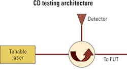
The use of a tunable laser that covers the S,C, and L bands (around 130 nm wide) and only looks for the fiber end, not all the events in between, solves all the previously mentioned issues (Fig. 1).
This is how it works: A first pulse is sent to verify the attenuation of the link, and then eight test signals are sent down the fiber with equal spacing, at wavelengths optimized for the measured attenuation and the proper fiber type. Eight points instead of four enables results for every fiber to be calculated, even those requiring five-term equations in complex networks made of several fiber types. Since only the fiber end is sought and because each wavelength has sufficient dynamic range (the tunable laser automatically selects eight wavelengths optimized for the span loss), testing is much quicker and each wavelength is much more accurate.
Using the aforementioned method, an enhanced single-ended CD measurement is obtained, but two boxes (source and receiver) would still appear to be required for testing PMD. However, as noted, the tunable laser mentioned in the previous section covers the S, C, and L bands and thus can provide a broad range of wavelengths. PMD is the average of differential group delay over all wavelengths and/or all states of polarization (SOP). By using the tunable laser to send two extremely close wavelengths through the fiber under test (at the same time) and then monitoring the delay between them, one can derive a local difference in transmission time
Repeating this process at several wavelengths along the tuning range and at various SOP (generated through a polarization scrambler) provides the mean delay or, in other words, a PMD measurement. As a result, what is actually measured is the local difference in transmission time between random pairs of closely spaced wavelengths and random SOPs.
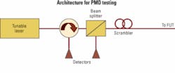
The addition of a polarization scrambler and a polarization beam splitter to the tunable-laser-based single-ended CD measurement mentioned previously can help users take advantage of this phenomenon. The inserted polarization scrambler will provide random polarizations for each different wavelength pair, and the polarization beam splitter in the return path will properly sample the returning signal (Fig. 2).
Test equipment based on the technique described here can accurately test PMD and CD from a single end – all at the touch of a button. Thus, there is no need to delay or cancel tests, which avoids interruptions caused by missing equipment or technician synchronization. This new technique can create a true all-dispersion unit that saves time and increases efficiency and ultimately opex savings. With accurate measurements at a reasonable price, networks can now be qualified with more certainty – without crippling the budget.
Additionally, a single unit means only one software application to learn and use, which simplifies training and minimizes human error. The output is one test file to manipulate instead of two separate files that need to be recombined. Another great advantage is the ability to test CD and PMD without disconnecting the fiber between the tests. Since more than 75% of network problems are caused by dirty or damaged connectors, less manipulation is always good news.
Francis Audet is senior product manager, Gwennael Amice is a senior application engineer, and Stephane Chabot is director of product management, Optical Business Unit, at EXFO Electro-Optical Engineering Inc. (www.exfo.com).

