Full-band chromatic-dispersion management improves performance
A new method of compensation based on high-order modes promises improved compensation for networks with high channel counts.
Yochay Danziger and Doug Askegard
LaserComm Inc.
Chromatic dispersion must be compensated within each channel and across the entire band, and it becomes even more of a challenge with the expansion into the L-band portion of the spectrum (1,570-1,610 nm), especially with the prospect of transmission rates of up to 40 Gbits/sec and beyond.
Conventional dispersion compensators are lacking in their ability to manage dispersion slope across the entire bandwidth, a critical requirement in the high-channel-count DWDM systems. Because these compensators cannot correct dispersion uniformly-they correct to a "center wavelength"-wavelengths at the upper and lower ends of the C-band spectrum are corrected too much or too little.What is needed is a solution that can manage dispersion across a wide spectrum, facilitating the migration from 2.5 Gbits/sec to 10 Gbits/sec in deployed WDM systems. Compensation by new high-order-mode technology matches the slope of chromatic dispersion, enabling full band utilization by next-generation ultra-long-haul systems that will provide long distances between regenerators and transmission at 10 to 40 Gbits/sec and beyond.
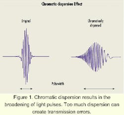
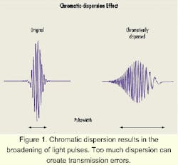
Although data pulses appear to be laser light either on or off, they actually contain a narrow spectrum of wavelengths. Any isolated pulse, even from a pure laser source, has a small spectrum by virtue of its modulation. As these pulses move through an optical fiber with positive dispersion (+D), the shorter-wavelength components travel faster than the longer-wavelength components, thereby broadening the pulse (see Figure 1).
This effect is called chromatic dispersion (or more precisely, group-velocity dispersion) and is due to the wavelength dependence of the group velocity of light in fiber. Chromatic dispersion, D, is measured by telecom designers in units of psec/nm-km-that is, the amount of broadening in picoseconds that occurs in a pulse with a bandwidth of 1 nm while propagating through 1 km of fiber.Chromatic dispersion causes intersymbol interference that results in bit errors when the effect exceeds the receiver's ability to discriminate between light pulses. When conventional singlemode fiber (SMF) is used in the third window of operation around the 1,550-nm region, where attenuation of the fiber is at a minimum, dispersion in SMF typically runs about 17 psec/nm-km. Although this amount is an issue in 2.5-Gbit/sec transport systems, it becomes a real roadblock at 10-Gbit/sec-and-higher transport rates. Without some type of dispersion compensation, the transport limit is about 60 km on SMF for a 10-Gbit/sec transmission rate.
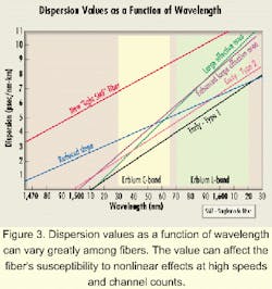
Chromatic dispersion has long been a factor in fiber design, and overcoming it has been one of the motivators for the creation of the wide variety of fiber types in use today. The newer generation of long-haul fibers, known as nonzero dispersion-shifted fiber (NZDSF), has lower chromatic dispersion. But since most of these fibers have increased dispersion slope (see Figure 3), dispersion management is even more critical, especially in DWDM systems. Note that for some of these fibers, dispersion at the high end of the C-band is nearly three times that experienced by the signals in the channels at the low end of the band.In most applications, the accumulated dispersion is compensated every 80 to 100 km along the singlemode fiber link-especially if an optical add/ drop is to be performed at those line amplifier sites. The issue of dispersion management becomes even more acute when the transmission rate increases to 40 Gbits/sec, as is illustrated by the deterioration of the eye-diagram shown in Figure 2 at the transmitter after 80 km in NZDSF-type 1, where the dispersion measured 260 psec/nm at 1,550 nm.
The slope-or rate of change as a function of wavelength-of chromatic dispersion is a very important factor to consider as the channel count of 10- and 40-Gbit/sec signals in crease to fill the C-band from 1,530 to 1,565 nm. Full bandwidth utilization means that there are large differences in dispersion between the longest and shortest wavelength used for the channels (see Figure 3).In light of this information, ideal chromatic-dispersion compensation solutions should have the following characteristics:
- Strong negative dispersion coefficient (shortens the length of the compensation fiber, if fiber is used as the compensating element).
- Low attenuationto minimize insertion loss.
- Minimal or no introduction of nonlinear effects.
- Dispersion compensation over a broad bandwidth.
- Correction of dispersion slope (second-order dispersion).
- Low or no dispersion ripple.
- Polarization-independent.
- Easy to manufacture to be able to meet demand.
Dispersion management is the process of balancing positive and negative dispersion over the length of the fiber transport network, so as the signals traverse the fiber, they always experience some chromatic dispersion, but when they reach the receiver, the total dispersion is near-zero or within an acceptable limit. As optical networking begins to become a reality, dispersion management will become more critical, since the optical signals must not have any accumulated residual dispersion. For example, while 2.5-Gbit/sec signals can tolerate up to 16,000 psec/nm of dispersion, 10-Gbit/sec signals can only tolerate 1,000 psec/nm since the tolerance is inversely proportional to the square of the data bit rate of the signals.
Dispersion management can be accomplished by a number of different methods. Lengths of transport fiber of opposite dispersion signs (+D and -D), with matching complementing slopes, can manage the dispersion, as is commonly done in submarine-cable deployments, but also create a difficult design and build problem-and is no solution for installed fiber. The first external solution, and still the most widely applied, is the conventional dispersion-compensation fiber (cDCF) compensator.
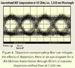
Conventional dispersion-compensation fiber (cDCF) is a special type of fiber that exhibits a much larger negative dispersion per unit length than the normal transport fibers shown in Figure 3, typically -70 to -90 psec/nm-km. One characteristic of cDCF is that its dispersion is nearly constant across the operational waveband (C-band). While this characteristic can neutralize the effect of chromatic dispersion at the specified center wavelength, the dispersion slope characteristics of the various transport fibers (see Figure 3) mean that DWDM transport channels away from the central wavelength may not receive adequate, or may receive too much, negative dispersion compensation.In a laboratory demonstration of this phenomenon, an 80-km length of NZDSF Early Type 1 fiber was used as the transport medium for 40-Gbit/sec NRZ signals. This fiber had a dispersion of approximately +260 psec/nm. Using a cDCF compensator of -260 psec/nm, the degraded signal previously shown in Figure 2 was improved to that shown in Figure 4 when the transmitted waveform was at 1,550-nm wavelength.
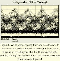
However, when the wavelength changed to 1,530 nm, the quality of the eye diagram degraded dramatically (see Figure 5). Again, the cDCF compensator is performing as expected, since at 1,530-nm wavelength, the dispersion of the 80-km length of NZDSF is only about +105 psec/nm; with a -260 psec/nm of compensation, the signal was experiencing about -160 psec/nm of dispersion (too much compensation at the shorter wavelengths). Similar performance happens at the long wavelengths of the C-band.Another limiting factor for cDCF modules is inherent in their fiber. To achieve the negative dispersion, the mode-field diameter of this singlemode fiber is made very small, so the effective area (Aeff) for the fiber core is in the 20- to 30-micron2 range. That limits the amount of optic power that can be put through the fiber before nonlinear effects become prevalent. Nonetheless, cDCF has been an attractive solution because it is completely passive, commercially available, and field-proven. But as has been shown, this solution does not compensate for the slope of chromatic dispersion.
Dispersion-compensation gratings are based on Bragg grating techniques, where a chirped pattern of index of refraction changes is impressed into the fiber core by UV light. This process effectively creates wavelength-selective mirrors.
It has taken years of development to produce dispersion gratings that are now just becoming available for narrowband compensation applications. Broadband compensation gratings, required for long-haul fiber applications, have proven very difficult to bring to market. Group delay ripple that manifests itself with rapid deviations from the mean dispersion slope of the grating over a range of wavelengths is the most serious problem. This wide deviation from the expected dispersion compensation at discrete wavelengths causes portions of pulses to shift in time, with respect to the rest of the pulse train, causing serious distortion.
Recently, some other new techniques have been demonstrated in lab experiments. Through further reduction in the Aeff of the core of DCF, some slope correction has been made possible for singlemode fiber. These new designs of DCF must operate at low optic power and are only used with the NZDSFs that have low slope dispersion.Interferometric techniques have also been demonstrated in lab experiments to provide dispersion compensation by providing wavelength-dependent paths of different lengths for different spectral components of the transported signal. These developments have yet to yield commercial products.
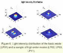
High-order-mode (HOM) fiber exhibits many of the desirable characteristics necessary for full bandwidth dispersion management. Modes can be thought of as guided optical waves, propagating with lateral distribution unchanged along the optical fiber. Mathematically, modes are solutions of Maxwell equations in the optical fiber, subject to appropriate boundary conditions. Depending on its dimensions and refractive-index profile, an optical fiber at a given optical frequency can support either:
- Many modes, as in a multimode fiber.
- A single mode (LP01), as in conventional singlemode fiber or NZDSF.
- Few modes, as in a few-mode (or HOM) fiber.
Only the fundamental mode (LP01) exists for all wavelengths. Each of the other HOMs has a cutoff wavelength above which it can no longer propagate. Modes differ from one another in:
- The spatial distribution of their amplitude and intensity (see Figure 6).
- Their phase and group velocities.
- Their dispersion properties (both dispersion and dispersion slope of HOM fibers can be controlled by their design as well as through the manufacturing process).
New dispersion-management devices based on HOM technology are now becoming available.
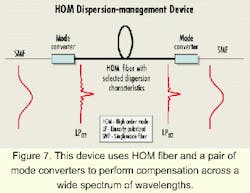
Chromatic dispersion can be effectively managed by HOM fiber; however, it requires that signal energy from the basic LP01 mode be transformed to a desired HOM and back to the basic mode. Figure 7 presents a schematic illustration of a HOM dispersion-management device.
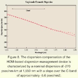
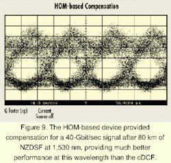
Figure 8 presents dispersion measurements at various wavelengths achieved by an HOM-based dispersion-management device, characterized by a nominal dispersion of -270 psec/nm-km at 1,550 nm with a slope over the C-band of approximately -5.6 psec/nm2.In contrast to the performance of cDCF, HOM-based slope dispersion-management means that the correct chromatic dispersion is afforded the signal across the bandwidth of the channel.
Figure 9 shows the results of dispersion-slope management from the HOM-based device where the 1,530-nm channel received the correct compensation at the same time as the 1,550-nm signal.
Chromatic dispersion is one of the main factors in the design of 10- and 40-Gbit/sec DWDM transport systems. Current techniques do not provide the correct compensation across the transport band, thereby limiting the span distance between regenerators. Carriers must demultiplex the multiple wavelengths into smaller groups of up to four channels each for effective compensation. This solution involves a very complicated architecture and incurs major expenses.
On the other hand, HOM-based dispersion-management devices are characterized by high negative dispersion, broadband slope correction, low loss, minimal or no nonlinear effects, and ease of manufacturing.
The slope compensation and lower noise means more channels can be accommodated with longer spans between regenerators. Thus, HOM-based dispersion-management devices open the bandwidth of deployed conventional singlemode fiber and newly designed NZDSF for current and next-generation transport systems.
Yochay Danziger, co-founder of LaserComm Inc., serves as chief technical officer of the company. He is based in the company's international headquarters in Tel Aviv, Israel, and can be reached at [email protected]. Doug Askegard is responsible for product planning, optical-network products, at LaserComm, which is headquartered in Plano, TX. He can be reached at [email protected].
Special thanks to Dr. Lara Garrett and Alan Gnauck of AT&T Research Labs in Red Bank, NJ, for their assistance making the 40-Gbit/sec measurements.
- I. Kaminow, T. Koch, "Optical Fiber Telecommunications IIIA," 1997.
- Y. Danziger, et al., "Applying High-Order-Mode Fiber Technology to Manage Chromatic Dispersion of SMF and NZDSF Across the Transport Band," Annals of 11th International Meeting on Electro-Optics and Microelectronics in Israel, November 1999.
- Gnauck, et al., "Dispersion and Dispersion-Slope Compensation of NZDSF for 40-Gb/s Operation over the Entire C Band," OFC 2000 post-deadline paper, March 2000.
