Managing the bandwidth autobahn
The challenges of deploying optical services in service-provider networks include deploying opaque architectures and migrating to transparent services.
John Adler and Mike StaufenbergCisco Systems Inc.As bandwidth-hungry network applications such as the Internet, e-commerce, and Web hosting continue to drive network growth, service providers face the challenge of expanding their architectures to meet the increasing capacity demands. Many service providers are turning to optical networking as a foundation for their next-generation architectures. To capitalize on an optical-networking solution, service providers should consider some central issues, including how to handle the great tides of bandwidth that flow between the long-haul and access networks and what is the best optical architecture to meet service needs.
An Internet Protocol (IP) + Optical mesh architecture, with intelligent optical switches serving as the gateways for the traffic between the core and access networks, answers both those questions. By deploying such an architecture in their network topologies, service providers can provide protocol/format- and rate-independent networks to deliver services in a more efficient manner.
To deploy this architecture now to meet current and future demand, several issues need to be addressed, including interoperability, planning complexities, and network management. For example, interoperability-a key issue when SONET/SDH was first deployed-arises again when considering the deployment of optical switches in the network. An optical switch that can't communicate with a carrier's DWDM elements and IP routers will create delays in the network lab due to the software changes, configuration adjustments, and overall additional time required to enable the switch to communicate with the other network elements. Such communication will be necessary to enable the provisioning, maintenance, and network operation centers to activate circuits and employ diagnostics in case there are problems on the network.
The deployment of optical switches involves complex planning. Optical networks may be divided into two types: transparent and opaque.
In a transparent network, optical signals are generated at appropriate lambdas and stay optical until they reach their destination. During the transport of a signal through the network, depending on the distance that it is traveling, there may exist the need for the signal to be optically amplified. But while it is on its way to its destination, the signal does not undergo optical-electrical-optical (O-E-O) conversion-it is not detected and changed back into an electrical signal, then changed back into an optical signal.By comparison, if an opaque network were to be deployed, there would be no signal that would be transported through the network elements without undergoing the O-E-O conversion process.
There are advantages to transparent optical switching in the IP + Optical network-principally, the fact that it can be less expensive than opaque switching. Performing O-E-O conversions requires a transmitter, receiver, and additional electronics for each pass through a network element. By reducing the number of O-E-O conversions, transparent equipment can reduce costs.
The other reason to deploy transparent network elements is they are indifferent to the protocol or format that passes through them. Protocol or format changes in the network would require changes to the router or other equipment at both ends of the circuit to format it as well as allow it to be provisioned and maintained properly. But the transparent network elements in between could remain unchanged.
Transparent networks have disadvantages, as well. One of the major drawbacks is that signal impairments will increase as additional spans are added to the network. Therefore, to meet and/or maintain a desired signal quality, the entire network needs to be engineered to accommodate all expected impairments before it is built. This requirement adds engineering complexity and cost to transparent networks. In addition, it would make additional network upgrades more complicated and expensive. By comparison, an opaque network can be engineered span by span as it grows with the traffic demand of the network.Another planning issue is that even though deploying optical switches solves bandwidth demand issues, it creates an additional problem in the central office (CO). Technicians installing equipment like digital crossconnects and SONET add/drop multiplexers (ADMs) in these locations face additional space and power issues when wavelengths are used from that CO. Since each ADM can handle one lambda at the OC-48 level, if there is customer demand for services at the DS-3 level or lower, the need to have equipment to meet this demand increases, as well.
Another planning issue that confronts the service provider is the amount of time it takes to provision a circuit in a transparent network. The largest carriers in the United States each have well over 150 points of presence in their networks. Provisioning an OC-48 service across the country requires a manual connection between DWDM terminals and the SONET add/drop terminals in each of the COs the circuit passes through.
Furthermore, it requires additional wiring through the fiber patch panels to additional ADMs and digital crossconnects to groom traffic below the DS-3 service level. Since the possibility of the circuit passing through a large number of rings is high, the network planner and provisioning center would need to identify and reserve the service and protect capacity for each customer that places an order on the network. Given this scenario, the time to provision the circuit could take from four to six months, which would not include setting up the provisioning in the access networks at both ends of the circuit.
One of the central issues in deploying all-optical networks is network management. In these transparent systems, there is a great amount of difficulty involved in monitoring signal quality as well as identifying the individual signals being transported.
This problem is most evident in the issue of signal impairments (i.e., optical signal-to-noise ratios-OSNRs) that can develop in the network, an example of which is finding faults in the network. For instance, signals being transported at the OC-48 and OC-192 rate would need to have an OSNR between 18 and 25 dB to keep a low bit-error rate (BER). In equipment that has a forward-error-correction (FEC) capability, the OSNR would show a relief of 3 dB and still be defined as having a good BER.But even though a signal may have adequate OSNR, it can still have electrical errors. That would happen if the optical monitoring is unable to diagnose faults caused by chromatic dispersion or optical nonlinearities such as cross-phase modulation. The end result is that the information obtained from the optical and electrical monitoring may not be enough to diagnose and resolve the problem. Until this disparity is resolved, optical switches will still be reliant on electrical information obtained via O-E-O conversion to resolve network problems.
It is clear from the tradeoffs between transparent and opaque approaches that carriers need systems that are futureproof and can support both these applications. Opaque designs can now be deployed that support photonically transparent services using adaptable architectures. This setup allows each carrier to get the immediate benefits of simple, easy-to-manage optical networks and a futureproof platform that evolves with technology.
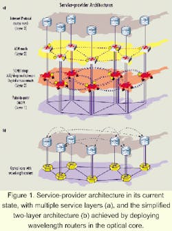
One approach is to use an architecture that deploys intelligence at the optical layer that can handle the optical bandwidth at the OC-48 and OC-192-and-above levels and still provide services at the lower levels, as well (see Figure 1). This architecture would be divided into two layers:
- Optical layer. The purpose of the optical layer is to deliver services at the higher bandwidth levels such as OC-48, OC-192, and when approved as a standard, OC-768. It would also manage wavelength-level transport with interfaces connected to service-centric platforms.
- Service layer. The objective of this layer is to deliver services to end users at the OC-12 level down to the DS-0 levels. These applications can be traditional voice and data services or new ones such as Web hosting, Internet access, and video streaming. The service platform at these levels would manage access speeds, the level of security that is required for the services, the quality of traffic on the network, and how to bill for the respective services.
In this new architecture, the old multilayer architecture of IP-ATM-SONET-Optical levels is transformed into a more efficient and flexible two-layer network. Under this framework, the SONET transport is assimilated into the optical layer. But in merging into the optical layer, the protection and restoration capabilities are not lost. Rather, the 50-msec restoration ability is kept, enhancing the flexibility to provide critical and noncritical services at those levels.
In this network, bandwidth is not provisioned according to the time-slot assignments (TSAs) available, but rather at the wavelength level. To be flexible and accommodate bandwidth demand, the ability to provision within hours and days instead of weeks and months becomes an absolute requirement. In this new network, new protocols pave the way to make the network more efficient and flexible to respond quickly to bandwidth demands and other service needs.
One such example of an open, IP/ATM standards-based protocol is the Wavelength Routing Protocol (WaRP), which was designed with three objectives in mind:
- Provide network restoration capability that meets the varied service requirements of carrier networks.
- Enhance the capabilities of the existing fiber, which is achieved by making the protection bandwidth flexible enough to adjust to the service provider's network needs. In addition, a class-of-service (CoS) designation is assigned to the connections. By defining the boundaries of the class of service, the protocol allows for the reduction of spare capacity while allowing a quality-of-service (QoS) connection to exist for those willing to pay for the service.
- Enhance the provisioning process by reducing the service interval required to turn up services. The software in the protocol allows the service provider to submit a request to set up a designated path on the network. The input information that would need to be provided would be the source, the destination, and the routing type. Once these boundaries are defined, the protocol can provision the service in a matter of seconds. Given the earlier example of provisioning a circuit, this procedure lessens the amount of work required to provision a circuit.
Today, a standard optical-network protocol for provisioning and restoration of the optical network does not exist. WaRP is an open protocol, developed prior to industry standardization and consistent with Optical Internetworking Forum and Internet Engineering Task Force work on extensions of Multiprotocol Label Switching into Multiprotocol Lambda Switching. As deployed proof points will shape the definition of the standardization efforts, WaRP provides the ability for carriers to deploy mesh optical architectures and upgrade seamlessly as the standardization bodies complete their work.
In examining how intelligent optical routing protocols can enhance system performance, it is necessary to understand the role that zones play in the core network topology and in broadcast control. The purpose of dividing a network into zones is to limit database size as well as the range of the broadcast packets. Each zone has a separate copy of the topology distribution algorithm. In addition, the nodes that exist within each zone contain information about their own zone. The topology of the zone is not known outside that parameter.
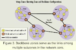
For example, nodes in the Backbone Zone contain information about the connections that exist in that topology. In addition, the nodes represented in Figure 3 are subdivided networks of the core. This backbone is different from an IP backbone in that in the routing engine it is a connection of two zones, whereas the IP backbone is the common connection for all zones within the network.
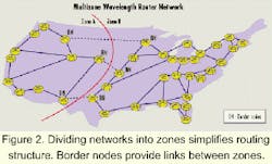
The links that connect nodes within the zone are called "intrazone" links. The best analogy is intra-LATA and inter-LATA terminology commonly used in incumbent local-exchange-carrier territories. The intrazone links would be similar to branch exchange connections made in intra-LATA regions, whereas "interzone" connections would be similar to connections between central offices in an inter-LATA (local calling) area. A diagram of zones is shown in Figure 2. Nodes that have at least one interzone link are also known as "border nodes."
Having this two-level topology (see Figure 3) provides several advantages to the service provider. For example, the size of the database used to maintain the nodes is reduced, enhancing the protocol's scalability for large network capability. The topology also limits the congestion caused by broadcast packets. Having a smaller scope of packet results in a lower number of hops being utilized and less traffic developing as a result. Shorter distances between nodes also allow faster restoration times, especially in large networks. Faster restoration times may allow the service provider the ability to make its services distinct from the competition by having this capability. Finally, since routing within a zone's parameters is based on information contained within that area, database corruption in one zone won't impair intrazone routing capabilities and the traffic that dwells within it.
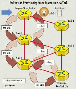
Another aspect of an intelligent routing protocol is the ability to provision wavelengths in the network and assist in lowering operational costs. In a traditional SONET network, each tributary provisioned in each ADM and the pass through in the entire length of the circuit requires configuration and control. This requirement results in each piece of equipment being provisioned as well as additional time and materials costs for the provider. It also can result in a large operational weight that could have a negative effect on the service provider's revenues.Figure 4. To provision a link between Boston and New York City, the provisioning technician enters a command via the management system by specifying the source, destination, protection type, and constraints that may be present in routing the request. Boston receives the request to provision and checks availability of a route to New York. With a route available, Boston sends a request-path request only to links determined by its routing table. Each node on the route makes a port selection, and capacity within each point-of-presence (PoP) is reserved as the "add path" request proceeds to New York.
By routing wavelengths on the core network, the service-provider provisioning engineers only need to specify the originating source and destination city. Instead of technicians going out and manually provisioning and turning up the circuit, the software and signaling utilizes the protocol to do the work from a central facility such as a network operations center (see Figure 4).
Another advantage that wavelength routing gives the service providers is it gives them flexibility in offering different levels of signal, depending on the QoS associated with that level. The classes of service are wavelengths classified according to the type of service desired, restoration levels, and other attributes that determine when the wavelength can be preempted, depending on the priority of traffic. In addition, other service needs such as latency and availability can be added, depending on the service provider's market demands and needs at any given time. These classes of service are arranged from 0 to 3 and described as follows:
- CoS 0 Low Priority Traffic. The basic attribute of a CoS 0 wavelength is that it's low-priority and can be interrupted by traffic that the customer deems to be more important. It also allows the CoS 0 path to become the protection path for the priority traffic.
- CoS 1 Public Internet. These wavelengths are assigned a path when it is provisioned and dependent on a slower version of restoration protocol for recovery. That is done by an algorithm utilizing a signaling packet to add a route for the rerouting of a designated wavelength around the network failure. Conflicts with resources are determined by the tandem nodes and resolved by the originating node.
- CoS 2 Premium Internet. This class of service is similar to CoS 1, with the exception that it uses a dynamic mesh restoration protocol to discover and establish alternate routes. It also is the only service class that can guarantee recovery in less than 50 msec without having to pre-establish the alternate route.
- CoS 3 Mission Critical Voice and Data Services. These wavelengths are assigned two distinct paths that are link and node disjointed. This service can guarantee recovery in less than 50 msec by pre-establishing an alternate route. The failure is addressed in this scenario by switching from one path to another.
Having these classes of service enables the service provider to enhance service offerings and increase revenues and provide quality products to the provider's customer base as a whole.
In the past two years, much attention has been given to the idea of the all-optical Internet in addressing the need for greater bandwidth. While it is wise to heed this call, service providers should not jump into these waters headfirst. Careful consideration and planning should be given to this issue with all internal parties involved in deciding how fast or slow to take this path.
- Cisco White Paper, "Controlling Optical Data Networks with an Application Specific Routing Protocol," Cisco Systems Website, 2000.
- Korotky, Steven K., Neil A. Jackman, Benny P.Mikkelsen, and Sunita H. Patel, "Optical Cross Connects for Optical Networking," Bell Labs Technical Journal, January-March 1999.
- Law, G., and A. Stewart, "Optical-Electrical-Optical Switching Offers Solutions, Challenges to System Designers," Lightwave, Vol. 17. Issue 8.
- Tomlinson, W.J., "Transparent Optical Networks: Where and When?" Tellium Website White Paper, 2000.
John Adler is director of marketing and Mike Staufenberg is product manager for optical solutions, Wavelength Routing Business Unit, at Cisco Systems Inc. (Richardson, TX).
The crossconnections are established and once the positive acknowledgement arrives at the hub in Boston, the path is provisioned.


