Electrical and photonic switching: Finding the right balance
Minimizing optical-electrical-optical conversions can save money and space, but electronics are still necessary.
LEE LIPES and JAMES ROUSE, Innovance Networks
Economic efficiencies in the backbone network historically have been achieved by substituting photonics for electronics. This trend started with substituting optical amplifiers for regenerators, which were required every 40-80 km. The reach capability of this vintage of equipment still required regenerators every 400-600 km, and transponders were necessary at multidirectional nodes to facilitate connection flexibility.
This trend continued with the rollout of ultra-long-haul (ULH) photonics and the optical add/drop multiplexer (OADM), which reduced the electronic conversion on a point-to-point span but still required electronic flexibility to network multidirectional sites. The next step in this historic trend, agile photonics, removes electronics from networking sites and extends the economic benefit of photonic networking across a larger portion of the network.
While this technology promises significant network savings, there are many functions required in the network that cannot be supported in the photonic layer, such as multiplexing, STS-1-based grooming, IP processing, or service-layer performance monitoring. The questions are, where do electronic and photonic technologies fit in the network and what's the right balance?
A little background first
Optical networks currently employ point-to-point line systems with OADMs incorporating back-to-back transponders at all multidirectional junction nodes. Back-to-back transponders are required at network flexibility points because of the analog engineering complexity and lack of a dynamic photonic system. Wavelength flexibility is achieved by terminating the photonic path with either a fiber patch panel interconnecting transponders or an optical-electrical-optical (OEO) switch.
The opportunity to remove unnecessary OEO transitions in the network is economically compelling. But network functions that demand electrical intervention must be accommodated. The majority of the connections in the long-haul market are IP- and STS-based and of subwavelength size. There are two primary networking appliances that will have direct connection to the optical layer to serve this demand: routers and STS-1-based electronic crossconnects. The IP layer can feed directly into the optical layer when port speed is OC-192 (10 Gbits/sec) or greater. When port speeds are smaller than this rate, the router port would be connected to a crossconnect for multiplexing up to the line rate.
To take full advantage of the cost savings provided by agile photonics, optimizing the grooming function toward the edge of the network must be realized. The implications of migrating the grooming function to the edge of the core must be examined in the context of the network as a whole.
North American core network
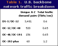
Consider a 100-node network model of the U.S. backbone. To create a traffic pattern, a distance-dependent, gravity-weighted model was created with data-centric cities heavily weighted; 3 Tbits of traffic, which represent about 15% of the total U.S. backbone capacity, were applied. The results are summarized in Table 1.
This groomed traffic is added to the A-Z demand between the 20-30 cities networked in the express layer and further adds to the fill in this network layer. The net result is that 70% of the wavelength-kilometer resides in the express layer, representing the largest source of traffic growth and cost in the network. The express layer still requires a moderate amount of grooming despite the relatively large amount of traffic carried between a relatively small number of nodes.
By routing traffic over the express network, the following characteristics appear:
- Average connection length in the network is 2,500-3,000 km.
- Average distance between nodes is under 800 km.
- 70-80% of the wavelengths at a given multidirectional junction on the express layer are passing through.
It therefore becomes evident that a solution is needed to address the reduction of connections passing through a node, resulting in a significant impact on the networks' operating efficiency.
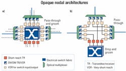
Opaque solutions make use of point-to-point line systems that require OEO conversions for transiting all fiber junction sites (see Figure 2). Two architectures are considered in opaque networking: patch-panel flexibility and electronic-crossconnect flexibility.
Since the majority of the cost in passing through a node is wrapped up in DWDM interfaces, a strong argument can be made to pass all traffic through an EXC core for operational simplicity. The EXC would be responsible for grooming and switching as well as regeneration and wavelength conversion. In opaque systems, the EXC acts as a large managed regeneration bank and the line system has a reach optimized around internodal spacing (600-1,000 km). Very-short-reach (VSR) technology is emerging, which will drop the cost of transition from the transponder to the switch and increase switch density. Every wavelength passing through this type of opaque node will require two DWDM transmitters/receivers and four VSR interfaces. As the node starts to scale, this solution can get quite costly and inefficient.
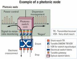
As an alternative, agile photonic technology is evolving to the point where a multiplicity of wavelength connection lengths can be accommodated on a single span. This ability, combined with photonic switching and ULH transponders, enables photonic bypass, which significantly alters the economics of backbone networking. Using these existing technologies, it is possible to take the EXC out of the line and move it in between the collector and express networks (see Figure 3).To compensate for removing regeneration, wavelengths would need to travel from source to sync in the optical layer, requiring a longer reach and more agile line system. The reach of an agile photonic layer needs to be optimized around path lengths (2,500-3,000 km) rather than the link lengths (600-1,000 km) required in an opaque system.
Advantages of a photonic layer
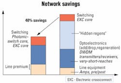
The average node in the network requires only 30% of its OEO interfaces for source traffic, regeneration, and intermediate grooming. The rest of the interfaces in the node are used to manage the wavelength-level interconnection between fibers. These interfaces are termed "hidden regens," since they are not actually required for regeneration. The resultant network cost diagram in Figure 4 shows that an agile photonic system has a 40% network cost savings as a result of hidden-regen elimination. In addition, hidden-regen elimination saves significant space and power. An example of the space and power requirements of a fully filled four-way site is shown in Table 2.
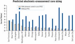
By tiering the network, pass-through traffic does not need to use switch ports on the subwavelength switch, greatly reducing the burden of the electrical-switch size. The use of multiple fabrics is minimized, thereby significantly reducing intra-machine connections that add cost and operational complexity. Figure 5 is a sample comparison of EXC sizing for the various architectural choices.
Balanced approachThere is an active industry debate surrounding OEO versus all-optical switching in the optical core, but next-generation networks will require both technologies. The function of subwavelength, either STS or IP management grooming, will continue, but building a 100% opaque network will cause serious space, power, and capital problems to go forward.A more economical approach is to drop and groom what's necessary, fill the pipes as full as possible at the edge, and establish transparent networking as deep into the network as possible. A marriage between electrical-switch functions at the edge and photonic networking in the core will deliver a more operationally agile, cost-effective core networking solution.
Lee Lipes and James Rouse work in the Network Architecture organization of Innovance Networks (Ottawa, Ontario).
REPRINTS
For information, contact
Kathleen McIntosh at:
603-891-9203, fax 603-891-0587,
or e-mail: [email protected].


