InGaAs detector arrays for monitoring the optical network
Between 1280 and 1620 nm, indium gallium arsenide is the material system of choice to fabricate low-noise and high quantum efficiency detector arrays for optical monitoring.
MARSHALL J. COHEN and KEITH FORSYTH, Sensors Unlimited
The ideal optical communications network is transparent, allowing data of any format to be aggregated and transmitted over a single high-bandwidth and low-loss physical layer without electronic regeneration at intermediate points. In a transparent optical network, digital signal quality monitoring information such as the SONET B-1 and B-2 bytes are not directly accessible, and other means of monitoring communication channel integrity and signal quality are required.
The importance of signal quality monitoring stems from the essentially analog character of optical-signal transmission. Effects such as fiber attenuation, amplified spontaneous emission (ASE) and pump noise in amplifiers, crosstalk in add/drop multiplexers, and wave mixing effects act cumulatively to degrade the signal-to-noise ratio (SNR) as soon as the signal leaves the transmitter. In addition, the performance of many optical and optoelectronic components varies with temperature and may degrade gradually over time, causing a slow reduction in SNR, increasing bit-error rate (BER), and eventually leading to failure. These fundamental attributes of optical networks have led to the development and wide application of performance monitoring techniques in the optical layer.1
Optical monitors may be divided into two broad categories: those with and without wavelength demultiplexing. Monitors without wavelength demultiplexing, commonly referred to as optical-channel monitors (OCMs), are used when there is only one optical wavelength channel per fiber. OCMs offer a lower-cost method of monitoring average optical power where wavelength demultiplexing is already provided by another network element or not required.
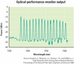
Optical monitors that include wavelength demultiplexing of the optical signal are commonly referred to as optical performance monitors (OPMs). The parameters that most OPMs measure directly are average optical power and wavelength, typically using a few percent of the signal power extracted from the transmission fiber (see Figure 1). From these direct measurements, a host of critical network performance parameters can be derived, such as channel presence verification, channel wavelength, ASE noise, optical-signal power, optical SNR (OSNR) per channel, optical-amplifier gain and gain tilt, optical-signal Q-factor, and estimated BER. These parameters may then be used to manage network reliability.A distinction may be drawn between optical performance monitoring and other kinds of signal monitoring methods, such as the use of pilot tones or a supervisory wavelength channel. A pilot tone is an amplitude modulation imposed on each wavelength channel at roughly 10 kHz. This tone is detected at network nodes to provide monitoring information. Disadvantages of this method include interference with various signal data formats, difficulty of extension to systems with many wavelength channels, and limited signal-to-noise detection capability.
A supervisory wavelength may also be added to the data wavelengths in a WDM system to provide channel-quality information. However, this method cannot determine OSNR variations with channel wavelength, a crucial piece of information for network management.
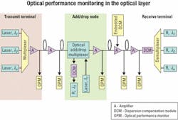
A common location for OPMs is at optical-amplifier sites (see Figure 2). Since the gain spectrum of optical amplifiers is a function of the wavelength distribution of input signal power, as well as a function of pump power and wavelength, input power variations in one channel produce gain changes in all other channels. Each optical amplifier also adds noise, thus reducing OSNR. OPMs located with optical amplifiers provide the feedback signal needed for dynamic gain flattening and other corrections to signal power in each channel.Optical add/drop multiplexer (OADM) sites are also candidates for locating OPMs. The power in added and dropped channels may vary widely over time, and an OPM in conjunction with an array of variable optical attenuators may be used to adjust channel power to the re quirements of downstream network elements. OPMs also allow prop er operation of the OADM to be verified, including channel location.
Monitoring optical switches, particularly switches based on micro-electromechanical systems (MEMS), is a useful role for OCMs. Verification of proper switching and beam alignment in a large number of channels can be performed at modest cost using OCM modules that require far less space than using a large number of single-channel pigtailed photodiodes.
OPMs with wavelength demultiplexing take WDM data from a single fiber, tap off a few percent of the optical power, separate the light into individual wavelength channels, and measure optical power as a function of wavelength. Demultiplexing OPMs can be further divided according to their method of wavelength separation-sequential wavelength scanning using a single optical detector or parallel output of many wavelengths using a detector array.
Although some OPMs employ tunable Fabry-Perot interferometric filters and single-element detectors and produce very low crosstalk and high wavelength resolution, most OPMs are based on some type of wavelength-dispersive element and a detector array. Array-based OPMs provide the reliability associated with having no moving parts and the efficiency of continuously using all available optical power. Demultiplexing elements used in commercial OPMs include arrayed-waveguide gratings (AWGs), reflective and transmissive diffraction gratings of various types, blazed fiber Bragg gratings, and integrated-optic Echelle gratings.2
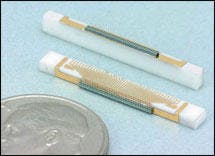
For operation in the three telecommunications bands between 1280 and 1620 nm, indium gallium arsenide (InGaAs) is the material system of choice for fabricating low-noise, high quantum efficiency detectors and detector arrays for optical monitoring.InGaAs arrays come in two basic varieties: parallel-output and multiplexed. Parallel-output arrays have one output node for each pixel, require one transimpedance amplifier (TIA) per pixel, and provide the lowest noise and largest bandwidth of the two. Parallel-output arrays are typically supplied in channel counts of eight to 64; for larger channel counts, the number of external amplifiers is usually prohibitive. Although most parallel-output arrays have a common-cathode design with separate anodes for each pixel, arrays with separate anodes and cathodes for each pixel are available, providing the lowest electrical crosstalk of any parallel-output design (see Photo).
Multiplexed arrays are recommended for pixel counts of 128-512, with 1,024-pixel arrays on the horizon. Multiplexed arrays integrate the input light signal over a fixed period of 10 microsec to hundreds of msec (depending on signal strength and dark current). They then sequentially scan and read out the signal from each pixel using an IC multiplexer with one or two output terminals. Thus, only one or two TIAs are required to read out a very large number of pixels.
The key performance parameters of InGaAs arrays for optical performance monitoring are quantum efficiency (QE), noise, dark current, dynamic range, and electrical crosstalk.
The internal QE of InGaAs arrays is approximately 80% over the S-, C-, and L-bands, and the external QE is greater than 60% over the same range. External QE can be enhanced in a particular band by optimizing the antireflection coating of the array for that band.
The electronic noise performance of InGaAs detector arrays depends on the type of array (parallel-output or multiplexed). Typical parallel-output arrays operated at zero bias voltage have noise levels on the order of a few femtoamps root mean square (RMS) per root hertz of circuit bandwidth. Temperature affects noise in these arrays mainly by causing dark current to vary and therefore the shot noise of the dark current. This effect is usually of minor significance.
The noise of multiplexed arrays is typically specified in terms of electrons per readout, since for most operating conditions the readout noise of the multiplexer dominates the total noise of the device. Readout noise of InGaAs detector arrays typically varies between a few hundred electrons per read to roughly 10,000 electrons per read, depending on the speed of readout, internal gain, and other application-specific parameters. Readout noise increases as the square root of the absolute temperature, a relatively weak effect over the typical operating-temperature range of telecommunications equipment.
Although not a property of the detector array per se, the design of the external amplifier circuit may have a profound effect on noise performance. Since noise voltage scales as the square root of system bandwidth, amplifier bandwidth in an OPM should not be larger than necessary to pass the information of interest.3 Manufacturers of low-noise operational amplifiers also provide application notes that discuss photodiode amplifier circuit noise and bandwidth considerations in detail.
Array dark current is a function of both array design and applied bias, and limits OPM performance in two ways: by adding noise due to the shot noise of the dark current and setting a floor on the minimum average optical- signal power that can be measured. Except for applications requiring the largest possible bandwidth, operation of the array with zero bias voltage is recommended to achieve minimum dark current. Under such conditions, parallel-output detector arrays for OPM use typically have dark currents of a few picoamps. As with noise, array dark current increases with temperature, typically doubling for every 10°C temperature rise.
The dynamic range of an OPM may be defined as the ratio between the maximum and minimum optical power that can be measured. This ratio depends only partially on the array parameters.
The maximum signal power that will produce a linear detector response is typically 1 mW (0 dBm); higher signal power will usually produce a compressed (sublinear) response. However, the maximum optical power for linear operation can be increased by reverse-biasing the array-at the expense of higher dark current and noise. Also, compression at high optical-signal power is repeatable and can be accounted for in post-processing to measure higher signal power.
The minimum detectable signal will be set by dark current, noise, and external electronic signal processing, as well as crosstalk from nearby pixels in the array. If only a simple low-pass filter is used to process the diode array output and the external amplifier has suitably low noise and input offset and offset drift, the minimum detectable optical power will be determined by the combined effects of dark current, RMS noise, and channel crosstalk.
For a detection bandwidth of a few kilohertz, the contribution from dark current and noise will typically be equivalent to an optical power of a few picowatts to a fraction of a nanowatt. In the absence of crosstalk, that allows a parallel-output array with only the most elementary signal processing to provide a dynamic range on the order of 60-80 dB. Using additional signal processing, such as subtracting out the dark current after calibration over temperature, can increase potential dynamic range.
In most performance monitors, however, channel crosstalk determines the minimum detectable power and therefore the achievable dynamic range. Performance-monitor crosstalk can arise from either optical or electrical sources-and usually both are significant. Commercial AWGs, for example, have typical single-channel optical crosstalk of -25 dB, and many other wavelength-dispersive technologies have similar levels of optical crosstalk. Optical crosstalk below -30 dB per channel is possible but very difficult to achieve while maintaining the cost and size constraints imposed on an optical monitor.
Electrical crosstalk within the detector array varies over a wide range, with the best commercial devices exhibiting typical adjacent-channel crosstalk below -35 dB. By careful device design and proper biasing of detectors and guard rings, commercial detector arrays with adjacent-channel crosstalk <-40 dB have been produced.
In specifying or designing an OPM or OCM with detector arrays, the following steps will help ensure a workable solution:
- Determine measurement bandwidth and minimum and maximum signal power requirements. These requirements will determine the required detector array dark current, bias voltages, and external amplification.
- Establish the number of elements necessary to meet channel-count requirements or optical resolution. That may be between eight and 512 with the commercial technology avail able today. If more than 64 channels are required, a self-scanned multiplexed array is recommended. For smaller channel counts, a parallel-output array is recommended.
- Select a pixel pitch between 25 and 250 microns, depending on the array input optics.
- Decide on packaging requirements. Packaging can be a simple detector chip on a ceramic submount for OEM integration, a glass-window hermetic package for easy handling and simple integration, or a hermetic fiber-pigtailed package with optical-fiber input for each detector pixel. Many variations are possible to meet OEM requirements, including angled submounts for low optical backreflection in fiber-coupled packages, filters, or other optical elements directly bond ed to the detector array surface; flip-chip back-illuminated arrays to avoid wire-bond clearance issues; and incorporation of a thermoelectric cool er within the package for the lowest possible dark current and highest stability of response.
InGaAs detector arrays are a key component in both OPMs and OCMs, allowing parallel signal outputs without moving parts and providing sufficient sensitivity and dynamic range to meet the requirements of measuring high-performance networks.
Dr. Marshall J. Cohen is vice president and Keith Forsyth is product manager for optical modules at Sensors Unlimited (Princeton, NJ).
- Y.C. Chung, "Optical monitoring techniques for WDM networks," Digest of LEOS 2000 Summer Topical Meetings: Broadband Optical Networks, July 2000. Contact IEEE Lasers and Electro-Optics Society (LEOS) at www.i-leos.org.
- E.S. Koteles, "Integrated Planar Waveguide Demultiplexers for High Density WDM Applications," WDM: Critical Review CR71, SPIE 1999 (www.spie.org). Also, J.L. Wagener, et al., "Fiber grating optical spectrum analyzer tap," 11th International Conference on Integrated Optics & Optical Fibre Communications, Vol. 5, p. 65, 1997. Contact Optical Society of America at www.osa.org.
- J. Graeme, Photodiode Amplifiers, McGraw-Hill, 1995.


