by Masum Choudhury, Tom Marrapode, and Ariela Donval
As complexity increases, the need for higher optical power in point-to-point communication is becoming more important in today’s networks. However, a sudden rise in optical power level due to a change in configuration, such as bypassing or altering the transmission direction in a ring or spikes from erbium-doped fiber amplifiers (EDFAs) or external power sources, may cause irreparable damage to optical equipment, especially the receivers. Therefore, it is highly desirable to implement a protection mechanism with a wide dynamic range within the network that controls and regulates the power level for its long-term reliable operation.
Developed under a grant from the Bi-national Industrial Research and Development Foundation, a new passive optical device called a dynamic attenuator acts in similar fashion to an electrical zener diode to limit output power to a pre-assigned value irrespective of input power level within a dynamic range. It also can function as a fuse that protects the network from permanent damage if the input power exceeds this pre-assigned level; the device works as a normal fixed attenuator below this input dynamic power range. It has been designed in the popular LC male to LC female plug-type configuration for easy network installation. It can also be readily incorporated within other configurations, such as LC male to MU female, MU male to MU female, and SC male to SC female.
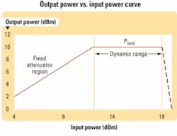
As the input power level increases and reaches a preset threshold, the scattering effect becomes significant whereby a fraction of the input power propagates to the output port and the rest is dispersed in the surroundings. With further increase in the input power level, the output reaches to a saturation limit, called the limit power (Plimit). The output power remains constant at Plimit up to the maximum applied input power, called the “dynamic range” of the attenuator, which is a reversible zone. Beyond this range the output power falls off sharply, thereby protecting the network from power surge. The concept for a dynamic attenuator with 10-dBm limit power is shown in Fig. 1.
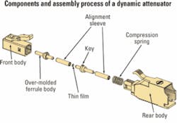
Figure 2 shows all required components and an assembly diagram for an LC male to LC female plug-type connector configuration. Two singlemode ceramic ferrules with an over-molded plastic key, called “plugs,” form the backbone of the device. The front and rear plastic housings have key pathways to maintain the necessary orientation at the angled physical contact (APC) interface.
With both ends polished, a singlemode fiber is first inserted into each plug and locked in place by a heat-curable epoxy. The shorter ends of the plugs are always APC polished, while the longer ends are either flat physical contact (PC) polished or APC polished depending on the connector style requirement. A nanostructure thin film is sandwiched between the APC polished short ends of two plugs inside a ceramic alignment sleeve. Another alignment sleeve is inserted through one end of the plug assembly over which sits the compression spring. This combination is inserted into the front and rear housing to complete the assembly process. The device then goes through an optical burn-in and temperature cycle schedule for about 20 hours to stabilize its thin film for normal operation.
The main function of the dynamic attenuator at powers above threshold level is to limit the output power to a predetermined level. Below the threshold it should act like a fixed attenuator.
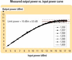
Figure 3 shows an experimental plot of the output power as a function of the input power for several wavelengths at room temperature. Here, the IL at low power is approximately 1.7 dB, whereas the limit power is about +10 dBm. The maximum input power design limit is around +18 dBm. Note that the graph depicts several power cycles, illustrating the reversibility of the power limiting operation. Also note that the curves are essentially identical for all wavelengths between 1,550 to 1,600 nm, an important feature for WDM systems.
The IL, polarization-dependent loss, and optical return loss of a 10-dBm device as a function of wavelength (from 1,510 to 1,610 nm) were measured to be ~1.7 dB, <0.1 dB, and <-50 dB, respectively. These device characteristics suggest that its inclusion in an optical network for protection and power regulation does not compromise transmitted signal quality.
Passive optical components such as the dynamic optical attenuator must adhere to some generic environmental requirements to achieve device compatibility with transmission networks. One of the most difficult operating environments is the uncontrolled temperature-humidity cycle (-40° to +85°C, 85% RH over 8 hours for each cycle) as described in Telcordia document GR-1209-CORE.
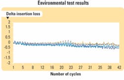
To simulate a field application, 14 samples (10-dBm limit power) were tested over two weeks (42 cycles) with the aforementioned temperature-humidity cycle with a continuous 5-dBm optical power applied to all the devices. During extreme temperature conditions in each cycle, the device’s ILs were measured. Figure 4 shows the change in insertion loss, delta IL, as a function of the number of cycles for the tested samples. As seen in Fig. 4, the maximum change in IL is only ~0.5 dB. This is well within the limit set by the Telcordia document, meaning all 14 samples passed the extreme environmental test.
Dynamic attenuators can regulate or control power and serve as a protection device in optical networks. They can either replace or complement existing power feedback control loops as an additional layer. In regulating power, they can equalize gain or power, or they can reduce power fluctuations in a long-haul optical signal transmission system. For example, the dynamic attenuators can be used at the transmission end of a DWDM system where a few sources of different wavelengths and power levels need to be equalized and multiplexed into a single fiber.
As a protection device, a dynamic attenuator can save detectors or receivers from over-power exposure and even increase the system’s dynamic range; also, it can work as a laser safety device. Telcordia test results strongly support that this device can perform equally well under extreme environmental conditions. Development is underway for other plug-type connector configurations, such as SC male to SC female.Masum Choudhury, PhD, is senior optical engineer within the Fiber Optics Division of Molex, and Tom Marrapode is director of marketing (www.molex.com). Ariela Donval is director of R&D at KiloLambda Technologies Ltd. (www.kilolambda.com). The work in this article was performed by engineers at Molex and KiloLambda.


