Recent developments have made ECDLs a cost-effective alternative for next-generation systems.
VINCE SYKES, K2 Optronics
The need for higher channel counts in DWDM networks has never been greater. As bandwidth requirements continue to escalate, vendors of both long-haul and metro DWDM equipment have set their sights and development efforts on more tightly spaced DWDM systems-at 50 GHz and below. In addition to boosting capacity, these high-density systems with thousands of channels are setting the stage for new applications such as routing and switching of wavelengths in next-generation optical networks.
However, many technical hurdles and technology limitations remain to be conquered, where precise, narrowly spaced, and stable wavelengths are required for ultra-dense WDM transmission. In other words, cramming thousands of channels down a single fiber places rigorous demands on the performance characteristics of light sources and introduces an entirely new set of design constraints related to spectral purity, wavelength accuracy, and stability, including laser aging effects associated with temperature drift and packaging.
These challenges have led to significant studies and refinements of existing laser technologies, resulting in several innovative and cost-effective DWDM sources-in particular, external-cavity diode lasers (ECDLs).
Although ECDLs have been commercially available for several years, recent advancements in the area of precise antireflection (AR) optical coatings, fiber- and waveguide-grating technologies, and optical device packaging have brought this technology to the forefront of DWDM transmission. Unlike distributed-feedback (DFB) lasers, where the Bragg grating structure is integrated with the active semiconductor gain stage, ECDLs employ a grating structure external to the laser-diode chip, resulting in a narrower spectral line width and spectral width (under direct modulation), higher wavelength stability, and lower chirp-ideal characteristics for narrowly spaced DWDM networks.Typically, DFB laser diodes have line widths of tens or several hundreds of megahertz, and their frequency is still sensitive to changes in temperature and injection current. This sensitivity is due to the internal built-in grating within the active region of the laser, making it more susceptible to temperature changes and variations of carrier density in the cavity. Several frequency stabilization schemes have been employed to compensate for this sensitivity in DFBs. The tradeoff is increased system cost and complexity as additional devices such as wavelength lockers and external modulators are utilized to enhance performance.
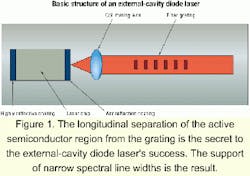
On the other hand, very narrow line widths and high-frequency stability are inherently achieved with external-cavity lasers by simply using mirrors and external gratings as optical feedback elements (see Figure 1). The longitudinal separation of the active semiconductor region (which provides gain) from the grating (which provides wavelength stabilization) is what gives an external-cavity laser its unique advantages in stability and spectral line width.
The basic structure of an external-cavity diode laser in Figure 1 consists primarily of an AR-coated diode laser (e.g., a Fabry-Perot) and a grating (e.g., a fiber Bragg). The main idea is to improve wavelength and temperature stability, including the dynamic spectral line width of the laser. That is accomplished by placing the semiconductor laser within an external cavity. The external cavity selects the emission wavelength by inserting a fiber or waveguide grating into the laser cavity. The front facet of the semiconductor chip facing the grating is coated with an AR coating to suppress self-lasing between the front and back facets and extend the resonator cavity beyond the laser chip. Thus, the coating prevents the laser from operating in a mode determined by the facets, and forces it to operate in a mode determined by the external grating.Conversely, the back facet is coated with a highly reflective coating to increase the power and reflect the light out the front facet. The light emitted from the front facet is collimated onto the grating, and the first-order diffraction beam is directed back into the laser chip. Here, it is amplified and coupled out of the laser as the zero order diffraction beam. Although the edge-emitting diode laser emits a range of wavelengths, only a narrow range of wavelengths returns to the laser chip for amplification.
The quality of the AR coating determines many critical operating characteristics of the laser and is critical to achieving singlemode operation with narrow line width. Employing AR-coated diode lasers with a residual reflectivity below 0.05% over a broad spectral gain region is now possible with state-of-the-art deposition methods and in situ monitoring techniques. These high-quality AR-coated laser chips also can be manufactured in high volumes and at relatively low cost for commercial deployments.
The ability to select one or more wavelengths in external-cavity designs is very important, as well. Both the fiber and waveguide gratings used in external-cavity lasers have improved significantly over the last several years. Today, tolerances of 0.1 nm or less for central wavelength and bandwidth are now commonplace and readily available using ECDLs. Such precise tolerances eliminate the need for thermal tuning and provide accurate International Telecommunication Union (ITU) grid light sources off-the-shelf. Precise thermal tuning is still required for DFBs to achieve similar wavelength tolerances.
To provide proper operation of the ECDL cavity, several design and packaging issues must be addressed. Fiber gratings, when used with single-chip designs for single-wavelength light sources, simplify the overall integration and packaging process. Waveguide gratings are inherently more complex but have advantages in multiple emitter chip designs and serve as the basis for optical integration of other components. For example, this area is where a substitute for a single-emitter version of a tunable laser could be offered. In this type of wavelength-selectable device, the laser could contain multiple gratings in increments of 4, 8, 16, etc. Wavelength selection would be accomplished by selecting one of the grating pathways to produce the desired wavelength.Such optical packaging issues-which include mechanical and environmental stabilization, particularly accurate alignment of all components-are key factors in a successful design. The entire laser cavity is temperature-stabilized with a thermo-electric cooler to ensure that environmental and on-board heating effects are minimized. Another area requiring emphasis is the optical coupling interface between the laser chip and the grating. The coupling must be precisely aligned to reduce coupling loss, which in turn maximizes the output power and minimizes the threshold current.
It is also necessary to achieve proper mode-size matching between the laser-diode chip, with a mode size of about 1x2 microns, and the circular mode of the fiber, with an average diameter of 10 microns. Magnification may be achieved using a lens integrated on the fiber. This technique leads to alignment tolerances of about 0.1 micron. It is possible to decrease such demanding alignment requirements by using laser chips with spot-size conversion.
As mentioned earlier, a major benefit of external-cavity lasers is the narrow spectral line width generated by these devices. The line width of an ECDL is inversely proportional to the square of the external-cavity length.
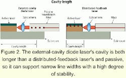
As illustrated in Figure 2, the cavity length of an ECDL is much longer than that of a DFB. While semiconductor laser chips are less than a millimeter long, ECDLs have cavity lengths of several millimeters. Thus, even for short cavities in the single-millimeter range, a very narrow line width can be obtained. Also, given that the cavity is passive, it is less sensitive to optical feedback, adding to the stability of the device.
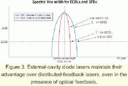
Figure 3 shows a comparison of the spectral line width of DFBs and ECDLs at -3 dB and -20 dB. As indicated, ECDLs provide a very narrow spectral line width, making them ideal for DWDM systems requiring tight channel spacing.
Operating characteristics such as wavelength, threshold current, and output power are all subject to small variations in temperature for both DFBs and ECDLs. As temperature changes occur, the refractive index of the semiconductor changes, which in turn causes a change in the effective length of the laser cavity and subsequently the resonant wavelength.
However, this phenomenon has less of an effect on ECDLs than it does on DFBs. In an external-cavity design, the semiconductor chip forms only a small portion of the overall cavity (see Figure 2). Consequently, changes with respect to the semiconductor or temperature have a smaller effect on the optical performance. On the other hand, variations in temperature have a more pronounced effect on DFBs, since the semiconductor chip forms a larger proportion of the optical cavity-with a DFB, the semiconductor chip is the optical cavity.
A typical DFB laser exercises a wavelength shift of about 0.1 nm per degree centigrade, and an ECDL an average of 0.02 nm per degree centigrade (see Table). This parameter (wavelength drift with temperature) is a function of the ratio of the active cavity length versus the total cavity length and can be manipulated to achieve desired results.
It has been widely demonstrated via existing commercial products as well as several new developments that ECDLs can produce a peak output power of 3 to 5 mW kink-free; a threshold current below 20 mA; a differential Q efficiency above 0.1 mW/mA; a RIN less than 135 dB/Hz; a line width of less than 1 kHz; and a side-mode suppression ratio of more than 40 dB. High-frequency modulation performance has also been demonstrated, with the only limiting factor being the cavity length.
As mentioned, the cavity length also determines chirp and temperature dependence of the wavelength, two areas where ECDLs outperform DFBs-mainly because of the longer cavity. Finally, even when all tradeoffs are made on the cavity length to optimize other areas, ECDLs still meet all requirements for OC-48 direct modulation.
Today, ECDLs offer breakthrough performance for ultra-dense WDM networks, combined with dramatically reduced cost and exceptionally high yields. Ongoing developments seek to exploit both the stability and tunability aspects of external-cavity laser diodes.
Vince Sykes is director of product marketing for K2 Optronics Inc. (Sunnyvale, CA).
To get the quickest response to your question, contact the appropriate person listed below.
Reprints, Bulletin Board
Kathleen McIntosh
Tel: (603) 891-9203
E-mail: [email protected]
Subscriptions, back issues
Michelle Blake
Tel: (603) 891-9360
E-mail: [email protected]
New Products, Calendar, People
Leah Gladu
Tel: (603) 891-9219
E-mail: [email protected]
News, features, letters
Stephen M. Hardy
Tel: (603) 891-9454
E-mail: [email protected]
Media kit, editorial calendar
Hilary Lloyd
Tel: (603) 891-9218
E-mail: [email protected]
Paid subscriptions
Omeda Customer Service
Tel: (847) 559-7520
E-mail: [email protected]


