Fiber Bragg grating technology passes light to new passive components
In DWDM applications, which require the filtering, combining, and routing of light, fiber Bragg gratings serve as a key component.
FRANCK CHATAIN, Alcatel Optronics
Operators are accelerating deployment plans for high-performance telecommunications systems to keep up with the explosive growth in bandwidth demand. A proliferation of new optical devices is accompanying this network evolution. Advances in optical transmitters, amplifiers, frequency converters, filters, and multiplexers are enabling new ways to generate, condition, and detect light. As a result, system manufacturers are pushing their component suppliers for more sophisticated solutions and reduced development and delivery times.
Passive components have emerged as strategic components in telecommunications systems, because these devices don't require external power to accomplish their functions and such components fulfill essential tasks all along the transmission link. With their unique properties, passive components have become critical for terrestrial and submarine telecommunications system designers.Fiber Bragg grating (FBG) filters have received particular attention due to their versatility, unique filtering capabilities, ease of use, and the potential to integrate these filters with other components.
FBGs have emerged as important components in a variety of lightwave applications. These filters have unique filtering properties, because light can be passed directly from another fiber via splicing, minimizing loss and avoiding the need for potentially costly optics to couple light between fibers and bulk components. The arrival of FBG technology could not have happened at a better time for rare-earth-doped fiber.
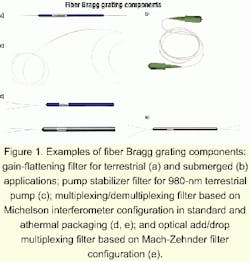
It is well known that the performance of an erbium-doped fiber amplifier (EDFA) is affected by the characteristics of the pump-laser diodes. Pump-laser performance is often adversely affected by unwanted external reflections back into the laser cavity and by temperature and injection current fluctuations. The introduction of FBG-based pump stabilizer filters resolves this problem by locking the emission wavelengths of 980-nm and 1,480-nm pump lasers and providing immunity to spectral-mode hopping due to changes in temperature, drive current, and optical feedback. These filters, used in both terrestrial and submerged applications, require a recoating of the fiber instead of the packaging used in complex and temperature-compensation filters. The key characteristic of an FBG-based pump stabilizer filter is its bandwidth and reflectivity with respect to the pump laser's characteristics and the particular application (see Figure 1).
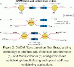
Another FBG application is directly related to the mass production of multichannel amplifiers. Because EDFA gain can fluctuate within the transmission spectral window, it is necessary to equalize gain across the spectrum with the use of FBG-based gain-flattening filters. Available in C-band, L-band, S-band, and for Raman amplifier applications, these unique components can reduce the non-uniform gain variation across the full EDFA window, improving performance and simplifying the design of WDM and DWDM systems (see Figure 2).EDFA designs may vary, however, based on the manufacturer or system. Thus, gain-flattening filters are generally customized products, corresponding to a system's gain characteristics. When manufactured using mass production techniques, gain-flattening filters are generally delivered in a thermally compensated package for terrestrial uses and a standard package for submarine applications, where temperature variation is of less concern.
FBGs can be used to solve another problem along a transmission link, as compensation for chromatic dispersion. The chromatic dispersion on the fiber inherent in optical transmission can cause significant distortion of optical pulses, leading to severe systems penalties, especially when upgrading systems to 10 Gbits/sec or higher rates. Compensation of this distortion is achieved by passing the distorted signal through a device with dispersion equal to that of the transmission fiber, but of the opposite sign. That can be done individually with a single-channel compensation (individual chirped gratings are required for each channel), or with the use of a single, very-long-chirped grating that can compensate over the entire DWDM band.
FBGs can support other functions, as well, such as combining, routing, and filtering the different signals along the link. These kinds of functions become more and more important as the number of transmitted wavelengths increases and the channel spacing decreases. Mass production of FBGs with bandwidths narrow enough for use in DWDM systems with channel spacings of 100, 50, and 25 GHz is now possible.
The main characteristic of an FBG is to act as a reflective filter. The first filter based on FBG technology was designed to select and isolate wavelengths as a reflective bandpass filter. In this device, the grating was written in a manner to reflect the desired wavelength according to the Bragg condition and to let the other wavelengths pass through the device. This filter required an optical circulator positioned just before the grating for a drop function to re-route the selected wavelength or just after the grating for an add function. These routing functions can be used in filtering applications or WDM systems or introduced into optical add/drop multiplexing devices thanks to optical circulators.
A slightly more elaborate design, based on FBG technology combined with fused-fiber technology in a Michelson interferometer configuration, can serve as a drop device without the use of an optical circulator to get back the selected wavelength corresponding to the Bragg condition. In this configuration, two FBGs, resonating at the same wavelength, are positioned in parallel and the reflected wavelength is dropped from the device after the coupler on a second fiber (see Figures 1 and 2). Thus, the same dropping function has been performed without the use of an optical circulator.
A more complex design can integrate the add/drop functions simultaneously in the same device. This design combines FBG technology and fused-fiber technology in a Mach-Zehnder configuration. In this device, two couplers are necessary-instead of one as is used in the Michelson interferometer configuration-between which two FBGs are written resonating at the same wavelength. This function is not easy to realize in mass production because the length of the two different arms of the device must be equal and the fused-fiber technology must be well controlled (see Figure 1).
Since most FBG components are not standard products but customized to resolve particular customer requirements, FBG technology requires technical expertise and flexibility. Packaging know-how is also essential for such products, particularly the thermally compensated packaging required for terrestrial applications.
The future in passive products belongs to the innovative. After meeting the challenge of wavelength selection in DWDM systems, FBG technology today is permitting Raman amplification to become an industrial reality for ultra-long-haul systems. In the future, FBGs will provide new solutions for routing and switching all-optical networks.
Franck Chatain is a product-line manager at Alcatel Optronics (Nozay, Paris region, France). He can be reached via e-mail at [email protected].
The fabrication of fiber Bragg gratings (FBGs) requires knowledge and competence in optical, chemical, and mechanical technologies. Fabrication is achieved by following specific steps:
- Hydrogenation of the fiber to increase its photosensitivity within the absorption bands used for the writing at 248 or 193 nm.
- Stripping of the coating of the fiber, which is not transparent to ultraviolet (UV). This can be done mechanically or chemically or both. It is important to note that this step has a critical impact on the final mechanical strength of the grating.
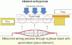
- Writing of the grating in the fiber (core or cladding) using interference fringes produced at UV wavelengths (193 or 248 nm) with a constant or variable pitch (fixed or chirped grating). During this step, it is often necessary to suppress secondary lobes to obtain acceptable performance in terms of crosstalk, with an apodization technique (see Figure). This consists of modifying the energy density all along the grating region (Gaussian shape UV laser beam or local interference fringes scrambling).
- Re-coating of the grating to allow manipulation (acrylate material or mechanical package).
- Stabilization of the grating to guarantee the lifetime of the product for terrestrial or submarine applications (typically 15 to 25 years). The aim of this annealing is to reduce the contrast of the effective index modulation and rapidly evacuate the hydrogen introduced during the first step of the complete process from the core of the fiber.
- Measurements of the main parameters of the grating.
It is important to note that all these steps apply to standard fibers, polarization-maintaining fibers, and photosensitive cladding-specific fibers.


