Optical protection: Get to grips with downtime
By Abe Queller
Lynx Photonic Networks
With their demand for bandwidth rising inexorably, enterprises are now, more than ever, dependent on the reliability of their networks for business continuity. And with downtime costing anything from € 1200 per minute for retail businesses to as much as € 90,000 per minute for the big financial firms, it should come as no surprise to find that blue-chip corporates are increasingly intolerant of network failures.
To protect against such eventualities, firms demand high network availability from their service providers. The "Five Nines" standard (network downtime of no more than five minutes per year) is now commonplace, with service-level agreements often specifying hefty penalties for failure to meet these stringent availability requirements.
For the service providers, the only logical response is to beef up those money-spinning enterprise networks with redundant routers, switches and line cards - though it's worth noting that redundant equipment is useless without an efficient way to access it. Ultimately, it's down to the network operators to deploy monitoring and control systems that can best exploit spare equipment to instantly and automatically restore faulty connections.
Ease of recovery
Network outages generally occur as a result of fibre breaks or equipment failure (faults in DWDM gear, routers, switches and the like). Redundant, diversely routed fibres can protect fibre links, while equipment failure can be counteracted by employing spares. This spare gear can run continuously in parallel with the primary equipment (a costly approach as it needs two fibre pairs) or can be activated only if the main equipment fails. This latter scenario uses a single fibre link, but the secondary equipment must be easily reconfigurable for fast connection to the link if a fault occurs.
One way to deal with fibre and equipment failures is to reroute at the IP layer. Intelligent routers continuously update their internal routing tables to maintain a complete overview of the current network topology. If they detect a failure, in-built algorithms dynamically adapt the topology to redirect network links as required.
Network recovery using this IP-based mechanism is simple and requires no specialized equipment or software. The downside is that it only works if network nodes are linked via multiple routes (and while such routes are usually available in core infrastructure, edge and access networks don't always offer this option). Another limitation is that error detection and recovery can be slow, with recovery times typically longer than one minute.
Finally, the IP approach does not support link prioritization. For example, if a line card associated with a critical link fails, the router cannot substitute a line card associated with less-critical traffic. Consequently the low-priority traffic continues, while the high-priority traffic is blocked.
Many of these issues can be remedied by replacing IP-based recovery systems with physical-layer protection - in the form of protection switches. These subsystems provide high network availability at lower cost ($20,000-60,000, or € 16,700-50,000, compared with hundreds of thousands of dollars per unit for redundant equipment), and allow fast and efficient network recovery (equipment switchover times as short as 6 μ s). They can be deployed in all network topologies, offering a high level of resilience even in networks using nonredundant lines.
What's more, protection switches enable networks to utilize all of their operational resources and recover from failures in a shorter switchover period. Switches usually reroute signals to redundant links or equipment in less time than it takes for the routers to detect a problem. Recovery at the physical layer, before any IP-layer rerouting takes place, minimizes the overall network impact.
While physical-layer protection can take place in the electrical or optical domain, optical protection switching offers several compelling advantages, such as comprehensive protection against transceiver failure. Optical switches are also data-rate and protocol-transparent, which reduces operational expenses as they don't need to be modified during network upgrades.
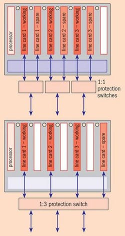
Traditional protection mechanisms use a 1:1 scheme, in which each primary line card is protected by a secondary card. This offers high reliability but at the cost of redundant cards and increased space, power and maintenance requirements. Additionally, when a single set of fibre pairs is used, only half of the router's throughput is utilized.
To reduce expenses, network operators are now moving to a 1:N protection mechanism. Because multiple concurrent failures are extremely rare, a group of line cards can be protected by a single spare card that is activated should any of them fail. When the problem is rectified, the spare is freed to provide protection from future failures.
A 1:3 protection mechanism, for example, saves two spare cards when compared with 1:1 protection of a three-line-card router (see figure below). Fewer spares means that protection is provided at a fraction of the cost. Utilization is also improved, as most of the line cards carry operational traffic.
Using protection switches does, however, need stringent reliability and availability criteria. For starters, these switches are installed to provide high network availability so it is not acceptable for them to fail. Ideally, protection switches should be based on highly reliable components and provide extended availability through redundancy. Support for extensive network diagnostics is also key--monitoring the switch operation enables administrators to spot a pending problem and rectify it before it causes an outage.
Protection switches must constantly verify the health of the spare modules, as well as of the switch itself, and confirm proper execution of any switchover operations. Moreover, they need to monitor any failed equipment following switchover to identify when the problem is rectified and trigger reversion to normal operation. Additional links such as loop-back connections and equipment-monitoring paths can support this functionality. A final criterion for efficient system utilization is that any redundant equipment can carry low-priority traffic while the system is not in protection mode.
One way to boost protection efficiency is by using co-operative protection modes, in which the protection switches and the routers that they protect coordinate their failure detection and recovery operations. Routers can best detect some of the failures, while the switches and their monitoring circuitry detect others. The co-ordination between the two is accomplished using either master/slave operation or autonomous operation.
In the master/slave operation, all of the switch's operations are controlled externally by the router or another designated control unit. Failures and other events detected by the protection switch are reported to the controlling unit, which issues the corresponding commands to the switch. This scheme supports centralized protection management, allowing dynamic changes to the recovery scheme based on network conditions.
While in autonomous mode, protection switches are preprogrammed by the controlling unit during reconfiguration to define failure conditions and recovery actions. Once programmed, the switch runs without needing support and the participating protection nodes handle failure detection and recovery locally. This scheme provides robust and fast protection, but requires the protection switches to contain failure-detection circuitry such as photodiodes and to respond to externally detected error conditions. They must also provide an intelligent control plane.
In either mode, the external controlling unit defines the switch activities. All events detected by the protection switch (including error detection, switchover, failure correction and reversion to a normal state) and all protection operations undertaken are reported back to this controller. The system administrator is also informed of these events for complete system visibility.
New generation
With the above requirements in mind, systems manufacturers are turning to a new breed of intelligent protection systems using planar lightwave circuits (PLCs). PLCs are based on solid-state technology and have no moving parts, making them highly reliable.
Rack-mountable, carrier-class PLC-based protection systems are available today in slim, 1U enclosures with redundancy features for high availability. Such equipment can operate in both master/slave and autonomous modes via an intelligent control plane. It also features photodetectors with programmable thresholds for fault detection. Switchover is triggered by internally or externally detected faults.
In the extremely rare event of multiple simultaneous failures, the line cards are protected based on a predefined priority scheme. Switchover and state reversion are accomplished through close integration between the switch and the router, and protection at the physical layer is accompanied by card configuration with the appropriate routing parameters.
Intelligent protection systems have extensive monitoring and diagnostics capabilities, allowing the switch to quickly identify a large number of failure types and detect when problems are corrected. The systems are configurable for line-card or port protection.
An example of such a product is the LightLEADER system developed by engineers at US subsystems vendor Lynx Photonic Networks. Built using PLC-based optical switch fabrics, LightLEADER allows switching from any optical path or fibre to any other, is data-rate- and protocol-transparent and can be configured as strictly non-blocking.
Looking ahead, it's clear that the development of this new type of intelligent optical protection switch lets network operators achieve cost-effective network availability and avoid the lost revenues and penalty payments associated with network downtime.
Abe Queller is vice-president of applications engineering at Lynx Photonic Networks, Calabasas Hills, CA, USA. E-mail: [email protected].
• This article originally appeared in FibreSystems Europe in association with LIGHTWAVE Europe, April 2004, p.13.

