An overview of VPLS
This companion article to "Multipoint PBB-TE and T-MPLS" covers the basics of virtual private LAN service as well as an overview of Hierarchical VPLS, which has been proposed as a way to address scalability concerns.
By DANIEL JOSEPH BARRY
TPACK
The basic defining elements of virtual private LAN service (VPLS) are virtual switch instances (VSI) and pseudowire (PW) tunnels. The VSI is a virtual MAC bridging instance with "split horizon" learning. Split horizon learning means unknown MAC addresses received from a PW tunnel will not be forwarded to other PW tunnels. This avoids learning loops.
The PW tunnel is used to transport traffic between VSIs in different nodes. A full mesh of PW tunnels is required to ensure that all nodes can be reached.
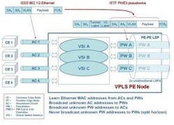
The following diagrams depict the basic operation of VPLS.
In Figure 1, the VPLS provider edge (PE) node is connected to customer edge (CE) nodes via attachment circuits (ACs) based on IEEE 802.1Q Ethernet. Each VPLS has associated VSI and PW tunnel instances. Ethernet packets from CE nodes are forwarded by the VSI to the appropriate PW tunnel for transport across the VPLS network (see Figure 2).
Each MPLS Label Switched Path (LSP) depicted is in reality two unidirectional LSPs, which combined provide bidirectional transport for each bidirectional PW. Three VPLS instances are shown (A, B, and C) supported by VSI instances in each PE node.
Establishing a VPLS network
A VPLS network is established by first defining the MPLS LSPs that will support the VPLS PW tunnels. The paths are determined using the Open Path Shortest First (OSPF) link-state protocol, which determines the shortest path for the LSP to the target destination. A full bidirectional mesh of LSPs needs to be established between all participating VPLS PEs. Label Distribution Protocol (LDP) or Resource Reservation Protocol (RSVP) is then used to distribute the label information to allow label swapping at each node.
Next, the PWE3 tunnels are established over the existing LSPs. LDP is used to exchange PWE3 labels in the case of RFC4762; in RFC4761, BGP would be used at this point.
For greater determinism and traffic engineering capabilities, it is possible to use the traffic-engineering variants of the MPLS control protocols to establish MPLS LSPs, such as OSPF-TE and RSVP-TE. For example, OSPF-TE will take bandwidth availability into account when calculating the shortest path, while RSVP-TE allows reservation of bandwidth.
As can be seen, VPLS is ideal in situations where a router network is already in place providing all of the control protocols required.
The VSI, as noted earlier, is based on a virtual MAC bridging instance. This is important to note, as it means that the MPLS mechanisms and tunnels are merely used as transport, while the intelligence lies in the MAC bridging that forms the heart of the VSI and therefore VPLS.
Pseudowires are generic and designed to be implemented on any suitable packet switched network. It is therefore possible to envisage a VPLS-like approach based on other tunnel mechanisms, such as T-MPLS and PBB-TE.
Hierarchical VPLS
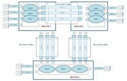
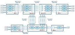
Hierarchical VPLS (H-VPLS) was designed to address scalability issues in VPLS, but has not done so to everyone's satisfaction. In VPLS, all PE nodes are interconnected in a full mesh to ensure that all destinations can be reached. In H-VPLS, a new type of node is introduced called the multi-tenant unit (MTU), which aggregates multiple CE connections into a single PE. This reduces the number of PE-to-PE connections (see Figure 3).
The MTU is connected to the nearest PE using a "spoke" PW. PE-to-PE PWs are now referred to as "hub" PWs. Full connectivity is only required between PEs, which allows more linear scaling of the network, but only to a certain extent. It still doesn't address the central issue of scalability and complexity in the PE network itself.
One possible solution could be to reduce the number of PE nodes to a minimum, possibly to just one. This would result in a single PE node with spoke PWs only. Since every PE needs to maintain the same information, there would be no extra burden on the central PE in this scenario.
The complexity would arise from establishing PWs to each new client, but this would need to be performed in any case. Even the single point of failure that this approach presents can be addressed with redundancy. Nevertheless, there are not many deployments of this type of single-PE architecture, so it remains to be seen what complications it might present.
Daniel Joseph Barryis director of marketing at TPACK (www.tpack.com).


