CWDM systems are considered a low-cost alternative to DWDM systems. They take advantage of low-cost, uncooled distributed feedback (DFB) lasers and less stringent wavelength multiplexing and demultiplexing components.
Individual CWDM filters typically are required to have at least a 13-nm-wide flattop passband, with small passband ripple and sharp spectral skirts, centered on 20-nm spacings on the ITU wavelength grid. The coating challenges for a CWDM thin-film filter (TFF) are far less than those of its DWDM cousins, making them less expensive to manufacture. In addition, with most applications needing only four to eight wavelength channels in the near future for the metro/access markets, inventory management of filter types is easier than in the DWDM situation, which further enhances the cost-effectiveness advantages of CWDM components.
Without fundamental technological changes, the optical layout and packaging requirements for multiplexing components become significant when they are asked to keep pace with the changes caused by a system-design shift to CWDM. More specifically, CWDM multiplexing components face the following challenges:
- Small component size so that a multichannel CWDM line card-integrating multiple wavelength transceivers with a multiplexer in a single module-is possible.
- Low insertion loss that minimizes or eliminates the need for amplifiers.
- Excellent temperature-dependent performance and reliability so they can be used in uncontrolled environments.
Two main CWDM multiplexer candidates are in the marketplace to address these challenges: those based on cascading three-port TFF devices and those based on free-space cascading of TFFs or what can be called the compact CWDM (CCWDM) package.
Figure 1 shows both approaches. A three-port filter for a particular CWDM wavelength channel consists of a lens to collimate the optical beam from a common port, a TFF of that wavelength channel to pass or reflect the beam based on its wavelength contents, and a second lens to refocus the transmitted beam to a transmission port. The TFF rejected beam will be bounced off the filter and past the same first lens, but it will be refocused to the reflection port.To make a CWDM multiplexer, several three-port filters are cascaded in such a way that each filter’s reflection port is connected to the subsequent filter’s common port. The connection between two components is through a fiber splice. Due to the limitations from the minimum bend radius of a fiber circuit, the dimensions of the packaging cassette cannot be reduced significantly. In fact, air occupies most of the current CWDM package space, which typically comprise 110×80×12-mm housings containing the three-port filters and their interconnecting fibers.
A CCWDM approach, however, yields a more compact form factor. Adjacent channels are cascaded, not through a bulky fiber cascade solution but rather in free-space, under collimated beam conditions. By removing the fibers inside the device cassette, the CCWDM box dimensions are only 41×28×8.7 mm, or a volume 10 times smaller than the standard approach.
To reduce or eliminate the use of optical amplifiers in a CWDM system, it is critical to minimize the insertion loss of a CWDM multiplexer. The root causes of CWDM device loss are collimator-to-collimator coupling loss and filter loss. Since the three-port cascaded filter approach uses roughly twice the number of collimating pairs than the CCWDM approach, it has intrinsically higher insertion loss, especially in the case of large channel count.
The worst insertion loss among channels of an n-channel three-port CWDM and CCWDM can be estimated as Σ(ILcollimator)n+Σ(ILfilter,R)n-1 +ILfilter,T and ILcollimator+Σ(ILfilter,R)n-1 +ILfilter,T, respectively. More specifically, a three-port CWDM typically uses GRIN lens collimators whereas the CCWDM usually uses C-lens-based collimators to reach long working distance. In either case, the practical pair collimator loss is around 0.2 dB. However, the total number of collimators is less in the CCWDM, resulting in a lower overall collimator loss. Filter reflection loss is typically below 0.005 dB to achieve transmission isolation requirements of 30 dB. Filter transmission loss is typically below 0.15 dB to meet reflection isolation requirements of 15 dB.
By using the formula above, it can be seen that the three-port cascaded filter approach can offer 0.97- and 1.79-dB worst insertion losses for four-channel and eight-channel multiplexers, respectively, while the CCWDM approach delivers 0.37 and 0.39 dB for the same two cases under the same assumptions, respectively.
It should be pointed out that for a CCWDM module, the best loss performance could only be reached when all pairs of collimators are perfectly matched (i.e., when the beam waist for each pair of collimators can overlap). In the ideal case, an n-channel CCWDM needs n+1 different types of collimators, which is not practical for mass production. In reality, one or two types of collimators are assembled on one substrate.
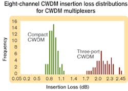
Thus, some collimator pairs do not meet the ideal condition of perfect matching, leading to higher losses than what is quoted above. Figure 2 shows typical insertion loss distributions of a three-port cascaded filter eight-channel CWDM multiplexer and its CCWDM counterpart at room temperature. CCWDM-based devices exhibit an average loss of 0.82 dB, while their three-port counterparts have an average of 2.1 dB.Another important aspect related to the insertion loss is the channel-by-channel loss profile. For many system applications, it is undesirable for different wavelength channels of data to attenuate differently along a transmission line. Thus, uniform insertion loss among channels is typically required.
From the loss estimation discussed above, large non-uniform losses are intrinsic to the three-port cascaded devices. In the eight-channel situation, for example, the differences can be up to 1.5 dB. To resolve this issue, the bare channels have to be matched one by one, and extra manual attenuations are added at fiber splices and/or transmission channels, leading to more production-cycle time.
CCWDM devices, however, have much lower collimator loss accumulation; this advantage gives better and more uniform loss control. Uniformity distributions of real eight-channel CCWDM devices are around 0.4 dB. For CCWDM, collimator mismatching is the main factor of loss difference. Uniformity can be improved by designing in more collimator types.
Many CWDM metro/access networks are now designed without temperature control measures. The deployed passive and active components must be able to work in ambient temperatures typically ranging from -5° to +65°C. New “industrial temperature” specifications have requirements as severe as -40° to +85°C. Maintaining relative positions among the optical subcomponents under these drastic temperature changes is a significant packaging challenge.
Different optical layouts between the three-port filter cascaded design and the CCWDM result in different packaging approaches, and the loss variation behavior is not the same between them. In the three-port cascaded filter multiplexer, the internal fiber splices contribute little to temperature-dependent loss (TDL). Each basic three-port filter, with a pair of pigtails, GRIN lenses, and a filter, however, is a major contributor to TDL. More specifically, for an eight-channel case, the individual filter reflection channel loss variations dominate the multiplexer’s overall module TDL. This loss is driven mainly by the stability of a filter, lens, and pigtail fixation scheme. Small and round bonding surfaces are the main cause of temperature instability.
A CCWDM device, however, uses a different optical approach. The collimators and filters are bonded on a common substrate, made of metal or glass, using an appropriate epoxy and curing process. Unlike the three-port filter, where the filter is attached by its smooth coating surface, a CCWDM filter is mounted through a rough filter sidewall. The bonding strength is much greater in the CCWDM case than in a three-port filter, which effectively minimizes reflected beam tilting-the dominant factor for overall TDL for the device. Additionally, each collimator in the CCWDM only has a single fiber pigtail.
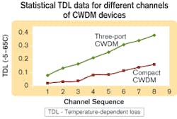
Figure 3 shows a comparison of typical TDL results for a three-port cascaded filter device and a CCWDM-based eight-channel multiplexer. Both TDL curves exhibit linear behavior, in accordance with the previous analysis. The slope of the curve for the three-port cascaded filter approach is steeper than that of the CCWDM, indicating the reflection channels of three-port devices are more sensitive to ambient-temperature changes.Manufacturing a good CCWDM device demands rigorous control of manufacturing processes. Fortunately, such process control does not require substantially different methods than producing a conventional three-port filter. Manufacturing control charts repeatedly show well-behaved normal distribution, with an average loss of around 0.85 dB and standard deviation of 0.096 dB. Assuming the loss specification for a typical eight-channel CCWDM to be 1.3 dB, which is already much better than the 2.5 dB for a typical three-port cascaded filter device, then the Cpk (process capability index) value is 1.67, indicating a stable manufacturing process.
Once an optical network has been installed, the service life becomes a major concern. Telcordia GR-1209-Core and GR-1221-Core specify a method to simulate real life conditions using various specially designed test procedures. These tests are generally considered applicable to component-level devices, like the three-port filters. The criterion for passing all these experiments is a <0.5-dB insertion loss change. Telcordia also specifies a module-level product performance and reliability through GR-63-Core, although its testing conditions are generally regarded as less severe than GR-1221-Core. Today, most passive-product suppliers simply test their devices through GR-1221-Core, with some selected module-level testing done under much less stringent conditions.
However, the reality is that for a single three-port filter, it is not very difficult to meet the GR-1221-Core tests by showing a <0.5 dB insertion loss change. But a cascade of eight such three-port filters that individually passed GR-1221-Core tests may have a maximum insertion loss change up to 4 dB, a condition that is not acceptable by any system integrator. To guarantee the overall insertion loss change remains within 0.5 dB during the service life of a multiplexer, the individual three-port filters’ reliability has to be far better than current testing specs require.
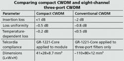
For CCWDM modules, the multichannel integration is done at the device level and on a common substrate within the package. Proper process methodologies and rigorous control steps enable qualification results in which all seven testing categories are well within the GR-1221-Core-specified pass/fail criteria. In fact, the greatest insertion loss change among samples subjected to the seven testing areas is 0.29 dB for the eight-channel case. Statistically speaking, for a three-port cascaded filter module to demonstrate this level of reliability testing results, the individual three-port filter’s GR-1221-Core testing criteria has to be set several times tighter than current levels.The Table shows a summary of the CCWDM versus a conventional three-port cascaded filter multiplexer for an eight-channel application. It is clear that the CCWDM technology not only offers a more compact package, but also lower loss, better uniformity, greater environmental stability, and a more reliable solution to current system requirements than its traditional counterparts.
Dr. Daoyi Wang is senior optical engineer, Dr. Chun He is engineering manager, and Dr. Yao Li is chief technologist at Alliances Fiber Optic Products (Sunnyvale, CA).


