Advanced chipsets make the next generation of high-speed hardware easier to develop.
MICHAEL DEPPERMANN,
PMC-Sierra Inc.
Bandwidth-hungry applications and incessant consumer demand force carriers to expand network capacity at an exhausting pace. Many carriers are relying on the tried-and-true approach of adding more switches and routers to keep up. Others are following the lead of long-haul networkers by installing DWDM systems able to carry up to 80 OC-48 (2.5-Gbit/sec) channels per fiber. But the central-office space needed for this additional equipment is often very limited, especially for network operators such as the competitive local-exchange carriers. Even when space is made available, the sheer mechanical and thermal requirements of more racks and boxes imposes a whole new set of problems that must be overcome before services even can be provisioned.
Then there's the shift in traffic mix. The world has embraced the Internet, and it is data-centric. Nevertheless, circuit-switching requirements remain and will persist well into the future. Because of all these factors, carriers are working feverishly with system designers to define scalable system architectures able to provide multigigabit capacity now and multiterabit capacity in the near-future. Both constituencies also realize these terabit-class switches and routers will need to do much more than pass cells and packets at much higher aggregate line rates.
Next-generation transport platforms must also be able to efficiently handle all the prevailing logical layer protocols. These include ATM, Internet Protocol (IP), Multiprotocol Label Switching (MPLS), Gigabit Ethernet, and circuit-switched time-division multiplexing (TDM). Providing this level of service elasticity at terabit-rate aggregate bandwidths will require an entirely new architecture. These systems will need a high-density switch core that manages switching of the massive traffic volume. They will also need potentially hundreds of line cards able to aggregate and process the varied services.
Today's OC-48 switches and routers hold, at most, 16 line cards. Installing hundreds of conventional OC-48, OC-192 (10-Gbit/sec), or even OC-768 (40-Gbit/sec) line cards into an existing Network Equipment Building System (NEBS)-compliant 19-inch equipment rack is simply not possible.Thus, supporting traffic demands at multiterabit aggregated line rates requires an entirely new packet-switching system architecture-able to support hundreds of line cards in multiple equipment racks that may require physical installation some distance from the switch core. This challenge can be addressed by using a new type of switching fabric and a direct line-card-to-switch (LCS) protocol. By taking this architectural approach, managing interprocess communication between multiple system elements at line rates of OC-192 and beyond becomes feasible.
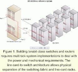
The LCS protocol allows for physical separation of the switching fabric and the line-card racks at distances up to 1,000 ft (see Figure 1). Since the switching fabric in these systems can be upgraded with the equipment in-service, scaling from tens-of-gigabit to tens-of-terabit capacity preserves the carrier's capital investment in the line-card racks.
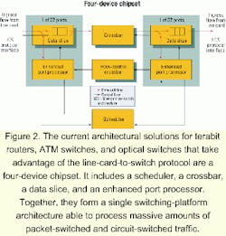
To build terabit routers, ATM switches, and optical switches that take advantage of the LCS protocol, a chipset is required. In this case, the chipset includes a scheduler, a crossbar, a data slice, and an enhanced port processor. Working together, the chips form a single switching-platform architecture able to support carrier-class, mixed-traffic networks (see Figure 2).The switching fabric supports line cards able to handle both circuit-switched TDM and packet-switched data traffic, including IP, packet over-SONET (PoS), ATM, and frame relay. Services can be provided in any combination at line rates up to OC-192 per port and up to an aggregate capacity of 320 Gbits/sec now and multiterabits per second in the next-generation chipset.
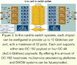
System chipsets existing today can be configured to provide up to 10 Gbits/sec per port, with a maximum of 32 ports. Each port supports either one OC-192 payload or four OC-48 payloads. A single-stage, unbuffered, and nonblocking switching fabric with virtual output queuing simplifies the implementation of the system's hardware and software architectures and offers highly predictable performance. Taking advantage of this LCS building-block approach, designers can create multiservice provisioning platforms (MSPPs) and DWDM systems that have substantial headroom and are futureproofed (see Figure 3).
Using the LCS protocol between line cards and the switch fabric also enables use of an unbuffered crossbar, allowing all the buffers to be placed on the line cards and under control of the traffic management device. As a result, the switch fabric doesn't require on-chip or off-chip DRAM.The interface between the switching fabric and the line cards can be implemented in two ways. In systems where the switching-fabric port is on the same circuit board as the line cards, an electrical interface can be used. In systems where the card rack is physically separated from the switching fabric, multimode vertical-cavity surface-emitting laser (VCSEL) array fiber-optic components are used. In this second configuration, the architecture enables up to 1,000 ft of separation between the switching fabric and line cards.
In operation, LCS can be viewed as a label swapping with flow-control protocol. As such, it allows designers to develop hardware without having specific knowledge of the switch core's port count. When data is sent into the switch core by a line card, it is assigned a label tag pre-agreed upon by both the core and card. The label indicates which switch core outputs should receive the data and at what priority.
Functionally, the switch core is assigned to deliver payloads from ingress line cards to egress line cards unchanged and without loss, while maximizing total throughput. That is done using per-queue flow control. Data passes between line cards and the switch core in 64-byte (or optionally, 76-byte) "cells" with an 8-byte LCS header. Being agnostic, the switch core makes no assumptions about the contents of the 64-byte payload. It could contain a fragment from a variable-length IP packet, an Ethernet or frame relay frame, or it could contain a complete ATM cell. By using this flexible processing approach, LCS is very useful in ATM switches, frame relay switches, optical switches, and IP routers as well as in Gigabit Ethernet, TDM crossconnect, and storage-area-network applications.
Transferring data in LCS-enabled platforms is a two-step process:
- The first step involves a three-way handshake between the ingress line card and switch core. The ingress line card sends an LCS request into the switch core containing a label identifying the output destination(s) for the requested cell and its class of service. The rationale for using a label, versus an explicit bitmap indicating the cell's destination outputs, is to ensure link bandwidth is used efficiently. The label also allows line cards to be designed without prior knowledge of port counts and the classes of service the switch core provides. Thus, by using this labeling approach, LCS can support multiple generations of switch cores and thereby futureproof the design.
- In the second step, after the switch core has received the LCS request, the core schedules a time at some point in the future when the requested cell will pass through the switch core. When ready to accept it, the switch core retrieves the cell from the ingress line card by sending an LCS grant/credit signal. The line card responds by delivering the cell into the switch core, where it is routed to the designated egress line card(s). Because of distance variations between the switch core and potentially hundreds of line cards in different equipment racks, a cell may arrive before its scheduled time. To ensure the cell gets routed to its destination at the correct time, each ingress port of the switch core maintains a single FIFO buffer that detains cells until the predetermined transfer time. The FIFO as a single alignment buffer compensates for fiber-length differences.
The LCS protocol also provides house keeping functions, including fault isolation and self-test, while an in-band mechanism allows the switch core to be controlled from one or more line cards. Another mechanism provides for switch-core synchronization scheduling to a system-wide Stratum 1, 2, or 3 clock, and there is a link bit-error recovery feature.
Achieving service elasticity at terabit-rate aggregated bandwidths will require using an entirely new generation of carrier-class switches in the network's core, at the edge, and in metro markets. They will be built using high-density switch cores able to manage massive traffic volumes and will include hundreds of line cards used to aggregate and process varied service types.
Using the fault-tolerant and futureproofing LCS protocol, system vendors can design multiprotocol, clustered terabit-rate switches and routers compatible with future generations of equipment with even higher-capacity switch cores.
In systems where the LCS protocol and complementary chipsets are used, the switch core and line-card racks can be physically separate at distances up to 1,000 ft, which alleviates the space constraints carriers face in the central office.
Because it is highly flexible, the LCS protocol allows for in-service switching fabric upgrades that allow capacity scaling of carrier-class systems from tens of gigabits to tens of terabits, while preserving the capital investment in existing technology.
Michael Deppermann is director of marketing, Carrier-Switching Division, at PMC-Sierra, Inc. (Burnaby, British Columbia).


