SPECIAL REPORTS / Fiber and Cable
New fiber class improves cost per bit while foreseeing future system enhancements.
JIM RYAN, Alcatel
In the fast-paced world of optical networking, vendors continue to introduce improvements in their system designs to boost capacity. Two of the main techniques include increasing bit rate and reducing the spacing between DWDM channels. Equipment that features 50-GHz channel spacing is being deployed in service-provider networks, and 25-GHz spacing is poised to make its debut in the future. Also, 40-Gbit/sec systems are just around the corner. Dense channel spacing and higher bit rate pose different challenges to the dispersion characteristics of the optical fiber, and both must be considered for optimum performance.
Service providers are eager to deploy systems with channel spacing tighter than the current 100 GHz since it enables them to pack more channels onto a single fiber. More channels pave the way to more profits, because increased capacity on a single fiber improves the cost of transporting each bit.
There is a catch, however. To optimize tight channel spacing, service providers must overcome the limitations it introduces on the fiber connecting these new DWDM systems. Because the wavelengths are squeezed even closer together, they are more apt to produce cross-channel non-linearities (four-wave mixing and cross-phase modulation) when deployed on fibers with low-dispersion levels, such as the current generation of nonzero dispersion-shifted fiber (NZDSF). The only way to reduce non-linearities when deploying these systems on existing fiber is to space regenerators closer together. Unfortunately, that remedy offsets the cost savings afforded by the tighter channel spacing in the first place.
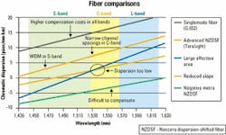
A more practical and cost-effective solution, available to service providers today, is to use a new class of advanced NZDSF fiber (A-NZDSF) that complies with the newly updated International Telecommunication Union (ITU) G.655 NZDSF standard. G.655 Table B (G.655b) was specifically modified to address the limitations current-generation NZDSF imposes on DWDM systems that use 50-GHz and 25-GHz channel spacing (see Figure 1).
When DWDM was first deployed commercially in the mid-1990s, vendors and service providers had problems getting the systems to work properly on the 0-DSF (dispersion-shifted fiber with zero dispersion at 1,550 nm) deployed in their networks. To their dismay, all the effort put forth to reduce dispersion to improve the transport of a single channel in the 1,550-nm window was causing all the problems-without the appropriate dispersion on the fiber, cross-channel non-linearities become severe.To better accommodate DWDM, the ITU in 1996 ratified the G.655 standard for NZDSF. The standard moved the zero dispersion point on fiber out of the 1,530- to 1,565-nm window where DWDM operates and replaced it with a maximum dispersion of 6 psec/nm-km at 1,565 nm. While that amount of dispersion in the C-band was sufficient to suppress non-linearities introduced by DWDM systems that use 100-GHz channel spacing, the minimum dispersion value has been increased in commercially available fibers several times as spacing has decreased.
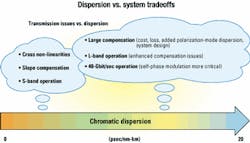
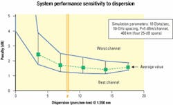
However, a repeat of the problem that inspired G.655 occurred when systems employing 50-GHz channel spacing were introduced. So the ITU ratified an update to G.655 in October 2000. With systems that feature ultra-dense 25-GHz spacing on the horizon, the need for the new standard has become even more critical. Tradeoffs must be balanced to obtain the optimum transmission (see Figure 2). To one extreme, low dispersion has more non-linearities when subjected to tighter channel spacing; high dispersion requires more compensation and has self-phase-modulation concerns with 40-Gbit/sec systems. A proper balance must be obtained.The new class of fiber described by G.655b features a maximum dispersion of 10 psec/nm-km at the end of the C-band to better suppress the increased non-linearities introduced by tighter channel spacing. At 1,550 nm, that correlates to a typical dispersion of 8 psec/nm-km. This amount of dispersion is high enough to minimize non-linearities, but low enough to minimize dispersion compensation needs and ease deployment of 40-Gbit/ sec systems (see Figure 3). The benefits of A-NZDSF to service providers deploying or upgrading long-haul or metropolitan networks are numerous.
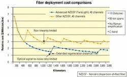
A-NZDSF's high dispersion permits even current 100-GHz DWDM systems to extend their reach, providing lower system cost (see Figure 4). That's because when non-linearities are suppressed optimally, the limiting factor in span length becomes optical signal-to-noise ratio (OSNR). And better OSNR can be obtained through higher channel power on a fiber with lower non-linearities. With such a fiber, DWDM systems with 50-GHz spacing will also have extended reach.Lower non-linearities enable the new fiber to delay use of the more expensive L-band, because it can carry more tightly spaced channels in the cost-effective C-band than standard long-haul NZDSF would be able to carry. The only way standard NZDSF could carry more channels in the C-band would be to cut the power used to launch each channel and limit the number of amplifiers, which in turn would decrease the maximum transmission distance before signal regeneration is needed.
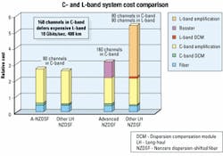
A-NZDSF can carry up to 160 channels of 10 Gbits/sec spaced at 25 GHz in the C-band, while standard NZDSF is typically able to carry only a maximum of 80 channels of 50 GHz in the C-band. It must carry the remaining 80 channels in the L-band. The cost of carrying 80 channels in the C- and L-bands is nearly double what it costs to carry all the channels in the C-band (see Figure 5). Adding the L-band is costly since both C- and L-band amplifiers are needed at each amplifier location.A-NZDSF is also particularly well suited to optimize fiber performance in both metro and long-distance networks. That's beneficial because by using fiber with similar characteristics for both long-haul and metro applications, service providers can make a seamless, less complex fiber transition between the two networks.
Fiber that complies with G.655b has less than half the dispersion of standard singlemode fiber (SMF/ITU-G.652). SMF's dispersion value equals 17 psec/nm-km at 1,550 nm, while A-NZDSF's is 8 psec/nm-km. That's important, because with the introduction of wavelength routing on metro rings, the limiting effects encountered along the length of the entire ring-not just each span-will hamper a carrier's ability to route wavelengths effectively. A 10-Gbit/sec ring of G.655b fiber that requires no compensation modules for distances up to 200 km will be better able to route wavelengths than a ring of SMF, which requires compensation for rings greater than 80 km.
A-NZDSF's higher-dispersion value combined with a low-dispersion slope provides another benefit. It provides a zero dispersion point below the S-band and positive dispersion above 1,440 nm. That enables DWDM compatibility across the S-, C-, and L-bands.
Due to the requirements of G.655b, a fiber designed for both C- and L-bands requires positive dispersion. Additionally, dispersion compensators that reverse the effects of positive dispersion are more widely available. Negative dispersion fiber, on the other hand, is typically compensated with spools of SMF that have a poor figure of merit (dispersion/attenuation) introducing high loss into the system and, thereby, reducing system reach.
With 40-Gbit/sec systems, unique challenges must be considered. While cross-channel non-linearities must be kept to a minimum for DWDM, self-phase modulation effects need to be controlled for higher bit rates. Fibers with very high dispersion, such as SMF, are more sensitive to cross-phase modulation. A-NZDSF achieves the ideal balance of dispersion-high enough dispersion for good cross-channel non-linearity management, and low enough for self-phase modulation control. By maintaining dispersion at half the level of standard SMF, A-NZDSF offers significant cost savings and easier system design when deploying 40-Gbit/sec networks.Typically, 40-Gbit/sec systems have a very low-dispersion tolerance and require that the dispersion slope must be corrected for each channel to arrive at the receiver with the same accumulated dispersion. A-NZDSF's higher-dispersion value makes it easier and less expensive to achieve 100% end-to-end correction of dispersion slope, compared to other NZDSF. Since both dispersion and dispersion slope are corrected by dispersion compensation modules (DCMs), A-NZDSF's higher dispersion requires slightly more DCMs and therefore obtains more slope compensation.
DWDM systems that employ 50-GHz spacing are being deployed today while vendors are poised to unveil systems that use 25-GHz spacing. Service providers that want to take advantage of these enhancements and the cost benefits they bring to the table can best do so by deploying them in conjunction with higher-dispersion fibers that meet the newly updated ITU-655 (G.655b) standard.
A-NZDSF's higher dispersion will help service providers lower their cost-per-bit by reducing cross-channel non-linearities and their limiting effects and therefore enables them to pack more channels into the cost-effective C-band. It also obtains optimum performance for future 40-Gbit/sec systems through nearly 100% slope correction and effective management of self-phase modulation.
With this latest ITU G.655 upgrade, service providers using A-NZDSF no longer have to choose between DWDM efficiency and higher bit rates. The dispersion characteristics of the new class of fiber are carefully chosen to support both possible future migration paths.
Jim Ryan is product manager for optical fibers at Alcatel (Paris). He can be reached at [email protected].
