Back to basics: DWDM components, configurations, and test equipment
As DWDM helps network providers meet the incessant demand for increased transmission capacity per fiber, system testing requires new measures.
STEFFEN VOGEL, Wavetek Wandel Goltermann
The digital age of voice and data-signal transmission began during the 1970s and has risen in tandem with the introduction and deployment of optical fiber into communications networks. The resulting increases in transmission rates attributed to this medium-from 1.5-Mbit/sec (DS-1) to 155-Mbit/sec (OC-3/STM-1) with the introduction of Synchronous Optical Network/Synchronous Digital Hierarchy (SONET/ SDH) standards-have fueled the ever-increasing demand for more bandwidth. With its bandwidth capabilities ranging into terahertz, optical fiber is the only transmission medium that can realistically cope with this exponential increase in capacity demand in the coming decades.
While voice traffic maintains a steady 7% annual growth rate (one billion telephone connections are predicted by the end of 2000), the increase in data traffic-particularly Internet traffic-is so great that the number of Internet connections is expected to rival those of telephone connections within 10 years. This increase is likely to lead to integration of voice traffic into data-communications services.
The global boom in the mobile-phone market has also affected developments in the fixed network. The number of mobile-phone users is expected to rise from 420 million this year to an astounding 940 million by 2005.Until now, it has been possible to meet the rising demand for bandwidth using time-division multiplexing (TDM) techniques. However, today's top bit rate of 2.5-Gbit/sec (OC-48/STM-16) stands to swiftly become yesterday's technology with 10-Gbit/sec (OC-192/STM-64) systems poised for widespread introduction. And many developers are already working on transmission rates of 40 Gbits/sec. In view of these technology advancements, it's not hard to see why today's TDM capacities lack the ability to handle the growing quantities of data being transmitted over wide area and, in particular, metropolitan networks.
Fortunately, a new technology appeared in the mid-1990s with a potential for future development that could not be guessed-dense wavelength-division multiplexing (DWDM). DWDM is a system for transmitting several optical channels simultaneously over a single fiber using the optical window between 1,530 and 1,565 nm. During its early stages, the number of channels available with DWDM was limited to four per fiber. That number has grown substantially since the introduction of DWDM systems in 1996; today, there are systems operating with 8, 16, 32, 40, 64, and even 80 channels per fiber. And if the systems manufacturers are to be believed, systems with 128 and 256 channels will soon become commonplace. A simple example may serve to illustrate such transmission capacity-by employing 128 wavelengths, each carrying 10 Gbits/sec, the resulting total transmission rate is 1.28 Tbits/sec.The key development that enabled DWDM technology was the availability of the optical fiber amplifier (OFA) for the 1,500-nm window. These amplifiers eliminate the need for expensive 3R signal regeneration-where the optical signal is regenerated with respect to time, shape, and amplitude-after each optical channel is transmitted a specific path length. The path length is now governed by the attenuation of the optical fiber. In contrast with 3R signal regeneration, where each optical channel is handled separately, the erbium-doped fiber amplifier (EDFA) amplifies all transmitted channels simultaneously.
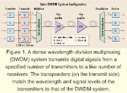
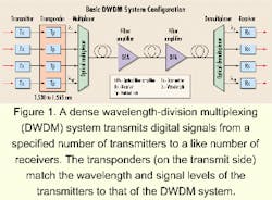
A DWDM system for transmitting digital signals from a specified number of transmitters to a like number of receivers comprises a range of transponders on the transmit side with laser wavelengths spaced on a 50-GHz /100-GHz grid as specified in the International Telecommunication Union-Telecommunication (ITU-T) Rec. G.692. This communications system also employs a multiplexer with a built-in booster amplifier, optical line amplifiers, and a demultiplexer that incorporates a receiving pre-amplifier (see Figure 1). The transponders are needed to match the wavelengths and signal levels of the transmitters to that of the DWDM system. If the transmitters generate signals suitable for direct connection to the DWDM system, the transponders can be omitted. Optical add/drop multiplexers (OADMs) and optical crossconnects (OXCs) are required to transition from an end-to-end link to a meshed photonic network.
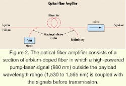
The OFA consists of a section of erbium-doped fiber in which a high-powered pump-laser signal outside the payload wavelength range is coupled with the signals before transmission (see Figure 2). Modern fiber amplifiers can amplify payload signals in the 1,530- to 1,565-nm range by 20 to 30 dB, allowing path lengths of up to 100 km.In addition to the payload signal in an OFA, there is a spontaneous emission of photons, which is also amplified. This interference signal, known as an amplified spontaneous emission (ASE), is relatively powerful and its spectral distribution indicates that the gain is largely dependent on the wavelength. If several OFAs are cascaded in a path section, the noise figure must be <5 dB and the wavelength-versus-gain characteristic must be as flat as possible. Using special technology, it is now feasible to extend the gain band of OFAs to 1,610 nm.
Optical multiplexers and demultiplexers are also key components in DWDM systems. A multiplexer has (n) number of inputs, each with a selective filter for the wavelength to be transmitted, and a singlemode fiber output to which the filter outputs are coupled. Multiplexers are identical in construction to demultiplexers and perform the same function in the opposite direction.
Different techniques are used to produce multiplexers and demultiplexers, including gratings, Bragg gratings, fiber gratings, Fabry-Perot filters, multilayer dielectric thin-film filters, Mach-Zehnder interferometers, arrayed waveguide gratings (AWG), and acoustic optical-tunable filters. The characteristics of the optical multiplexer/demultiplexer equipment determine signal-transmission quality. Therefore, this equipment should meet the following requirements:
- Insertion loss between input and output should be low.
- The insertion loss should be independent of polarization, otherwise the output level will vary.
- The passband (1-dB limits) should have a flat characteristic to compensate for small changes in operating wavelength.
- The filters should have a steep cutoff to avoid crosstalk from adjacent channels.
- The filters must be thermally stable.
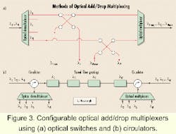
The task of the OADM is to uncouple one or more wavelengths modulated by the payload signal from a DWDM signal (drop function) and to insert signals with the same wavelengths but new payloads in their stead (add function), which can be achieved using different methods. One possibility is to use a combination of optical multiplexers and demultiplexers with two-way optical switches between them (see Figure 3a). A second option is the use of a tunable OADM, which is technically more complex. This option consists of a multiplexer, a demultiplexer, two circulators, and several tunable fiber Bragg grating filters (see Figure 3b). Available commercially since 1997, the technology on the market was limited to fixed OADMs with a maximum of 16 switched channels. The configurable OADMs shown in Figure 3 were recently introduced.
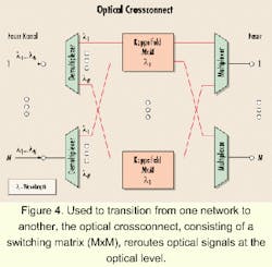
An OXC is a spatial switching matrix used in the transition from one network to another (see Figure 4). OXCs allow optical signals to be routed at the optical level, for example, when restoration is needed or if a backup circuit is required. Various technologies can be used to produce OXCs, each with different properties in regard to insertion loss, switching time, and cascading ability. OXC technologies include polymer, optomechanical, lithium niobate (LiNbO3 ), silicon dioxide (SiO2 ), and semiconductor (InP).It's conceivable in the future that the OXC will be the locations where the optical signal is regenerated with respect to time, shape, and amplitude (3R). OXCs with 16x16 up to 128x128 inputs/outputs will become commercially available this year. Devices with 256x256 and 512x512 inputs/outputs are expected to follow.
The characteristics of the optical fiber play an increasingly important role in the realization of DWDM systems, especially as signal bit rates increase to >2.5 Gbits/sec. Standard singlemode fiber, which conforms to the ITU-T Rec. G.652 specification and is already used in many networks, has chromatic dispersion of about 17 psec/(km-nm) in the 1,550-nm band, restricting the path lengths for transmissions at high bit rates. The chromatic dispersion can be compensated for using dispersion-compensating fiber of 80 psec/(km-nm) per fiber-km. But to ensure correct control of compensation, the chromatic dispersion must be verified in the field.Another type of fiber used in many networks is dispersion-shifted fiber (DSF), which conforms to ITU-T Rec. G.653. This fiber does not exhibit any chromatic dispersion in the 1,550-nm band. Problems do occur, however, when transmitting high bit rates in DWDM systems due to nonlinear effects such as four-wave mixing.
The polarization-mode dispersion (PMD) in installed singlemode fibers can also become a critical factor. PMD varies with time and is also affected by pressure, stress, and the fiber-bend radius as well as by changes in temperature. Fiber with poor PMD is sometimes encountered due to a lack of standardized cable-manufacturing processes in the past. Therefore, PMD must also be checked after the cable is laid to ensure that fibers with poor PMD are not used for transmitting high-bit-rate signals.Recently, fibers have been introduced that do not exhibit increased attenuation in the 1,380-nm band (OH absorption peak). These fibers have a transmission window from 1,300 to 1,620 nm, enabling the entire range to be utilized by DWDM systems in metropolitan networks, where optical amplifiers are not needed because of the short distances involved.
Although DWDM systems and components undergo intensive testing during the manufacturing and system integration stages, on-the-spot measurements during installation and acceptance remain essential because the characteristics of the fiber can only adequately be explored after installation. Environmental influences also play a role during this stage of implementation.
Attenuation is one of the primary characteristics of in-ground fiber that must be measured. Measurements are taken using either a loss test set consisting of a Fabry-Perot laser source and an optical level meter or an optical time-domain reflectometer (OTDR). The advantage of the OTDR is that it only requires access to one end of the fiber to perform measurements. It also renders the attenuation profile over the entire length of visible cable, while showing attenuation hits caused by connectors and splices. Joints, which may lead to increased reflection of the signal, can also be detected. It's important not to limit the attenuation measurement to one wavelength in the center of the transmission band; the wavelengths of the optical supervisory channel at 1,480 nm, 1,510 nm, or 1,625 nm should also be measured.
Alongside the attenuation and reflectance characteristics of the fiber, the effects of chromatic dispersion and polarization-mode dispersion (PMD) must be taken into account when transmitting at high bit rates over singlemode fiber. PMD is a basic property of singlemode fiber that causes the energy at a certain wavelength to split into two orthogonal polarization states. In an ideal fiber, the propagation times of the two polarization states are identical. However, production tolerances and differences in refractive indices create different propagation times in an actual fiber, which in turn leads to a broadening of the pulses, resulting in bit errors being detected after signal regeneration. The difference in propagation times is termed differential group delay (DGD), or delay time, and is measured in psec or psec/Ãkm. PMD is the root-mean-square of all different DGD values (due to different wavelengths) and is measured in psec or psec/Ãkm.
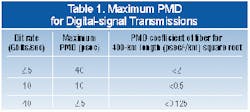
One of the difficulties inherent in PMD is that it's almost impossible to compensate for it because it varies with time. The maximum permissible PMD values for various bit rates are shown in Table 1.
Three approaches to measuring PMD have been standardized by the American National Standards Institute (ANSI-New York City) and the Telecommunications Industry Association/Electronic Industries Alliance (TIA/EIA-Arlington, VA):
- Fixed analyzer method (FOTP-113).
- Interferometric method (FOTP-124).
- Jones matrix intrinsic analysis (FOTP-122).
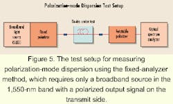
Both approaches require only an easy-to-use broadband source in the 1,550-nm band with a polarized output signal on the transmit side and no connections other than the device under test between the transmitter and receiver (see Figure 5).
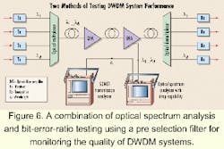
Numerous factors can affect signal quality when system components are connected to form a complete DWDM system. These factors include crosstalk, nonlinear distortion, ASE, gain peak, and dispersion. The bit-error ratio of the system, in which the effect of all of these factors may be seen, is calculated with an end-to-end measurement using a digital-transmission analyzer. It is still necessary, however, to take measurements of individual sections during system implementation using optical test equipment.
Unlike single-channel systems, DWDM systems require selective measurement techniques to test the signal levels and optical signal-to-noise ratios (OSNRs) of the individual channels as well as to characterize wavelengths. The exception is the use of conventional broadband-level meters to determine the overall loading. The OSNR measurement is particularly important since ASE noise accumulates with increasing path lengths. These measurement requirements place unique demands on the optical test equipment.
The optical spectrum analyzer (OSA) has become the workhorse for system commissioning, maintenance, and/or troubleshooting.
Apart from its optical characteristics, an OSA should offer portability, ruggedness, operate over a wide temperature range, and allow battery operation for on-site usage. Modern, PC-based OSAs also provide the advantage of remote-control operability.
The optical part of an OSA is realized using one of three basic technologies:
- Scanning grating monochromator.
- Scanning Michelson interferometer.
- Scanning Fabry-Perot filter.
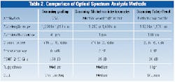
Table 2 compares the three methods of optical spectrum analysis. OSAs that use the scanning grating technique offer the greatest dynamic range, wavelength range, and measurement accuracy. The other two methods have limitations with respect to dynamic range (interferometer) or wavelength range (Fabry-Perot filter). The interferometer approach, however, provides the maximum accurate measurement for multiple-wavelength meters. The Fabry-Perot technique is often used to produce performance monitors embedded in the system.
Optimally, an OSA should provide facilities for monitoring the optical parameters of a DWDM system over an extended period of time to detect system degradation as it occurs. These results are stored to allow comparison with preset-limit values. A real-time graphical display of the optical parameters measured is another important requirement.Currently, network providers tend to focus on the concurrent analysis of optical parameters and transmission parameters at the digital level. Since checking wavelength, signal level, and OSNR does not detect all the possible causes of faults, this ability to filter out one channel from the multiplexed signal is important-especially when measurements are made at points where only the DWDM signal is present, for example, on optical amplifiers. This dropped channel can then be analyzed using a digital-transmission analyzer (see Figure 6). Fortunately, OSAs with this type of pre-selection filter function are commercially available.
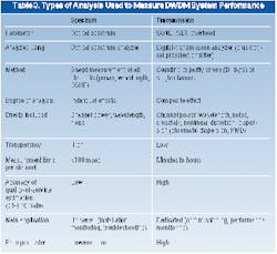
The two major measurement methods used to test DWDM performance are summarized in Table 3.
Along with the components used in DWDM configurations and the test equipment required for commissioning and maintaining such systems, significant developments are expected in the next few years in the various embedded techniques for monitoring operation, administration, and maintenance criteria; network-management systems that cover the optical layer; and the convergence of data and voice transmissions over a common layer (IP over DWDM). All of these areas are worthy of further attention. Although these systems are only just beginning to appear, the process of standardization will play a substantial role in the development and implementation of these networks.
Steffen Vogel is a product manager for fiber-optic test equipment at Wavetek Wandel Goltermann, which has headquarters in Research Triangle Park, NC, and in Eningen, Germany.
