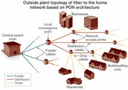
After 25 years of being the future of access networks, fiber to the home (FTTH) is now being deployed on a large scale in the United States. For several years, the ever-increasing number of FTTH deployments has been driven mainly by nontraditional carriers such as utility companies, municipalities, and home developers as well as a few CLECs. Today, however, FTTH also has become the technology of choice for many independent LECs and at least one large incumbent-both for new builds and overbuilds. The economic and technical reasons for this change have much to do with outside plant (OSP) innovations that reduce the labor and active electronics costs of an FTTH installation.
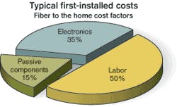
The labor necessary to deploy the OSP represents the biggest piece of FTTH first-installed cost (see Figure 1). The active electronic equipment in the central office (CO) or headend (HE) and at the customer premises (CPE) ranks second-even in PONs, where the equipment is shared among multiple subscribers and no active components are deployed in the field. Passive components installed in the CO/HE as well as the OSP complete the cost picture; they represent an opportunity for significant reductions in the first two cost elements.In the past, a typical installation used traditional technologies such as fusion splicing in the field for interconnection. Today, more advanced components can save the labor costs associated with such fusion splicing by using factory terminations, not only within the LCP cabinet but also for the NAP, drop cable, and NID. “Premier” offerings go a step beyond pre-termination and enable technicians to install complete links in a single step, thanks to the integration of hardware components (such as terminals) with the cable. In addition, it has become evident that the architecture of the OSP drastically influences the cost and complexity of deployment.
Let’s look at these factors more closely. Fusion splicing in the field requires highly skilled personnel, expensive equipment, and significant time to accomplish, especially if only a few splices have to be made at a single location. New factory-terminated optical connectors can be used in the drop section of the OSP to eliminate fusion splicing requirements. These environmentally sealed, hardened, and strain-relieved connectors for the optical drop cable assemblies and NAP terminals enable subscribers to be connected easily, quickly, and reliably when they sign up for service. Recent installations using such connectors have shown a time savings of up to 50% compared to classic deployment methods (i.e., fusion-spliced drop cable). Without the need to reenter the NAP terminal, sophisticated equipment and specially trained installers are no longer required, and the hourly labor rate can drop significantly-up to 40% depending on the carrier’s cost structure.
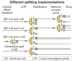
Meanwhile, the latest generation of OSP technology takes the pre-terminated idea one step further. NAP terminals with hardened connector capability are factory-installed on a distribution cable in a daisy-chain configuration, typically up to eight or 10 in-series. Field installations have shown that an installation that usually takes a full week can be done in a day. This approach requires fewer personnel and less expensive equipment, and already has proven its worth in the field.Finally, while generically defined as a cascaded star architecture (e.g., in the ITU-T G.983 and G.984 series Recommendations or the IEEE 802.3ah standard), PONs allow carriers different implementation schemes. As illustrated in Figure 3, an overall 1×32 split can be achieved by cascading a 1×8 optical splitter at the LCP with a 1×4 coupler/splitter at the NAP or with only a single 1×32 split at the LCP. The first scheme is typically called a distributed split (DS) and the latter a centralized split (CS) architecture.
The CS architecture has four main advantages over the DS, which makes it the solution of choice for most PON deployments:
• Single point of maintenance in the network. The typical test method via an OTDR can be used for testing the network in both directions from the LCP to the CO/HE and to the home. If a coupler/splitter is deployed at the NAP, as with the DS architecture, another truck roll may be required to determine if a problem is located in the distribution or the drop section.
• Splitter port utilization efficiency. With reasonable initial take rate assumptions, coupler/splitter ports installed at the NAP in a DS scheme may stay unused for a long period of time or, in a worst case, forever. In a CS scheme, ports of the first coupler/splitter installed at the LCP can be populated with subscribers across the complete distribution area until they are fully utilized.
• Coupler/splitter port-cost efficiency. Usually, a 1×4 coupler/splitter costs more on a per-port basis than a 1×8, a 1×8 more than a 1×16, etc. That may result in up to a 40% higher per-port cost when adopting the DS architecture.
• Optical loss optimization. Similar to the pricing scheme, the concatenation of couplers/splitters usually shows a higher insertion loss than a single component, because another interconnection point is introduced. Depending on the individual coupler/splitter and connector performance, that may result in a loss penalty of up to 1.5 dB.
The LCP cabinet needs to make the testing and incremental installation of couplers/splitters as easy, fast, and reliable as possible.
Multiple architectures can be used in FTTH networks, but PON is a very efficient configuration from an overall cost perspective. Although highly cost-efficient, this technology also imposes some technical constraints that must be appropriately addressed to optimize the network coverage and services.
There are two fundamental characteristics of a PON:
• It is, by definition, a “passive” network that requires active components (amplifiers, transmit/receive optics, media converters, etc.) only at its ends (i.e., the CO and the customer premises).
• Its efficiency is based on a power-sharing concept, where the same optical signal is shared among multiple subscribers.
These two principles make it clear that optical power availability is a key element in PON performance. The power launched at either the CO or CPE has to be enough to compensate for all losses introduced by all the components, connectors, splices, and the fiber itself, with enough margin to reach the appropriate receiver at an acceptable level. This margin can be improved in two ways.
The first is to reduce the loss of the individual network components. When using the pre-terminated components, optical connectors become a critical element. It is imperative to specify the maximum insertion loss of each optical connector (e.g., 0.2 dB for standard or 0.1 dB for loss-optimized SC-UPC and 0.3 dB or 0.15 dB for SC-APC style connectors, respectively). It is also important to use connectors that have proven their reliability in the OSP. In addition, specifying the splitter loss under all environmental conditions is as critical as asking for a full qualification report.
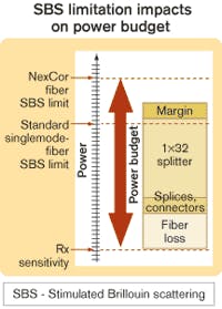
The second way to improve margins is to increase the launched optical power. OSP innovations have a role to play here as well. For example, standard singlemode optical fibers have a physical limitation called stimulated Brillouin scattering (SBS), which occurs when a high-power optical signal such as that required by analog video transmission generates an acoustic wave in the fiber. That causes refractive-index variations and ultimately reverse-direction scattering of the optical signal. As power levels increase so does the effect, resulting in transmitter signal loss and noticeable video-signal degradation at the subscriber’s TV.Figure 4 depicts the various components that contribute to optical power loss in the network and how the total of these loss figures compare with the SBS limit of standard singlemode fiber (SMF). As illustrated, standard SMF can present a challenge due to the hard limit imposed by SBS. Some cursory treatments of video-signal optical loss budgets fail to consider the true signal requirements of off-the-shelf commercial transmission equipment or account for all the passive elements and design considerations that contribute to the overall loss budget. When all signal requirements, loss components, and design margins are considered, there is a clear shortfall between the total OSP loss and required optical power for adequate video-signal fidelity.
This fundamental limitation constrains the PON power budget, imposing a limit on the maximum amount of power that can be launched by the transmitters, consequently imposing network reach and coverage limitations. A fiber that relieves the SBS limitation would allow more power-handling capability and thus greater flexibility in accommodating OSP loss requirements.
While relatively straightforward fiber-design techniques have been available for some time to address the SBS limitation, the challenge has been to develop an optimized fiber that also is completely backward-compatible with the installed base of standard SMF plant. This challenge has finally been overcome, enabling a fiber that provides both backward compatibility and a 3-dB increase in SBS threshold. Figure 4 also shows the additional margin such fiber provides, which makes the SBS problem significantly more manageable.
Both low-loss connectors and high-SBS-threshold fiber result in significantly improved optical power and loss budgets, amortizing the CO/HE equipment across a larger distribution area and/or more subscribers. Key to both advancements is the ability to integrate them transparently into existing craft practices by maintaining backward compatibility with existing infrastructure.
Network operators have multiple choices in their method to deploy FTTH to fit their unique circumstances. Recent advances in OSP components allow carriers to identify cost-saving opportunities while providing increased flexibility and high confidence in the network:
• Pre-terminated drop cable assemblies with environmentally sealed, hardened, and strain-relieved connectors, along with NAP terminals that do not require entry to connect subscribers, provide a clear advantage. These advances can save up to 50% of the time and up to 40% of the hourly rate to connect a subscriber.
• Factory-installed NAP terminals on distribution cables reduce the time to install the distribution portion of the FTTH network by up to 80%.
• CS architectures simplify network testing and maintenance and can save up to 40% of the per-port cost of the coupler/splitter.
• Low-loss connector technology guarantees a maximum insertion loss for every connector, providing the security to plan for the worst case. This technology furthers network reach and amortizes the active equipment cost more quickly.
• Full-spectrum optical fiber with higher SBS threshold that is 100% backward-compatible with standard SMFs simplifies PON deployment by eliminating the power limitation. It also reduces cost per subscriber through longer reach, larger coverage, and more efficient utilization of electronic equipment.Dr. Bernhard Deutsch is director, market development, at Corning Cable Systems (Hickory, NC). Robert Whitman is manager, global broadband market development, and Dr. Claudio Mazzali is manager, global market development, engineering, and analysis at Corning (Corning, NY). The authors would like to thank David Meis of Corning Cable Systems and Dr. Andy Woodfin of Corning Optical Fiber for their contributions.


