How invisible should your FTTH network be?
When we think of the general categories of communications network deployments in neighborhoods today, two main terms often come to mind: aerial and buried. Although there are variations of each in most systems today, almost every access network deployment can be binned into one of these two categories.
With FTTH activity increasing sharply in the United States today, a discerning eye has been turned toward the deployment approach and the visibility of these ultrabroadband networks within neighborhoods. In many, if not most, greenfield FTTH applications, developers and service providers alike are driving the network infrastructure underground. System invisibility has become the name of the game: The less telecommunications equipment you notice when traversing a development, the better.
While this deployment mantra is well founded, there are a host of key factors to take into account with respect to how much of the “buried” plant should actually be placed below ground. A look at several neighborhood deployment aspects reveals the issues that surround this question.
In a buried FTTH network, there are several key system components that can either reside above or below ground level. The figure on page 30 highlights the “neighborhood,” or distribution segment, of a typical FTTH network. In this diagram, two obvious locations in the distribution segment of the network stand out as candidates for placement either above or below ground level: the local convergence point (LCP) and the network access point (NAP).
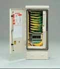
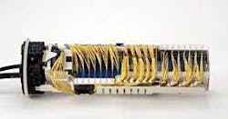
The LCP in a typical FTTH network is the point at which passive optical splitters (for a passive optical network, or PON) share the signals from feeder fibers with multiple subscribers via individual distribution fibers. These critical network components typically take the form of a small cabinet that is installed on a concrete pad or vault above ground level. As LCPs split a handful of incoming feeder fibers up to 32 ways each, just one of these components is required to serve a neighborhood in most deployment scenarios. Photos 1a and 1b show an example of an above-ground LCP platform, as well as a sealed, below-ground alternative.Since drop cables are directly buried or run through a conduit in underground deployments, detrimental factors like multiple lot crossings, street crossings, and higher installation costs per foot of drop cable account for the fact that the underground NAP serves smaller, more manageable zones than its aerial counterpart. As such, it’s a likely scenario to have considerably more NAP terminals installed in a below-ground deployment than in an aerial deployment passing the same number of residences. Consequently, the placement of these components now has much more impact on the operation, community acceptance, and survivability of the overall network.
To make the important decision of whether to install NAP terminals below or above ground level, we’ll highlight some of the key considerations that should be evaluated. Since nearly every FTTH deployment will have its own requirements, it’s not uncommon that two similar neighborhoods located across the street from one another could end up being serviced very differently from a network infrastructure standpoint.
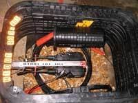
With the focus on buried network deployments today, let’s define the two predominant underground network NAP installation configurations-pedestal and handhole-and then compare the advantages and disadvantages of each. Photos 2a and 2b illustrate examples of NAP terminals installed in each of these configurations.Visibility. The first category for NAP placement consideration is that of component visibility. This may very well be the determining factor for a service provider on whether to place NAP terminals in pedestals or handholes. It should come as no surprise that the winner in this category is the handhole, which is installed in a “flush-to-grade”configuration. And while visibility is an important consideration, it’s not the only one to be made. Recent advances in pedestals have made these products a not-so-distant runner-up in this category. With lower profiles and smaller above-ground cross-sectional areas, the pedestals of today have become far less of an eyesore to residents and service providers alike.
First-installed cost. The first-installed cost factor has become increasingly important for FTTH network deployments. As is common in other segments of these networks, the installation labor often dwarfs the material cost of the component itself. The same can hold true at the NAP. While a very basic handhole and a pedestal can be in the same ballpark from a pricing standpoint, the handhole requires more site preparation and overall installation time. However, if a larger handhole or a higher strength rating is desired with these products, the price can easily eclipse even the most full-featured pedestals. As such, the hat tips toward the pedestal in this category.
Network accessibility. Looking beyond the installation on Day 1, special attention must be given as to how these products will be operated and accessed throughout the life of the network. The duration and complexity for each truck roll directly affects the bottom line for service providers. Because the NAP location will be visited for each drop cable connection of a new subscriber, the choice in terminal placement becomes a critical decision. Simplicity of terminal access, drop cable connection, transition, and routing all give the pedestal a slight edge in this category.
In all regions of the country, the cleanliness of the terminal installed in a pedestal configuration is generally much better than those installed in handholes. Even in the driest of areas, sprinkler systems and the infrequent downpour can turn handholes into miniature mud pools. Pedestals with sealed lids keep internal components high and dry, even when completely submerged as a result of the “bell-jar” effect. Finally, pedestals hold an advantage when it comes to access and ability to be located in cold-weather regions where snow pack can seriously impede the progress of technicians.
All in all, handholes are not far behind, but the added time required for access of the drop connection port, terminal sealing requirements, and cable entry and transition from this location tips the scales in favor of the pedestal for network accessibility.
Network survivability. The last major consideration that must be mentioned is that of network survivability. The key factor to weigh here is the nature of the environment of the deployment location. Distance from sidewalks, streets, intersections, and proximity to nonvehicular traffic all must be considered to determine the desired level of protection that is required. The simple statement “If you can’t see it, you can’t break it” best justifies the handhole as the superior approach to address this factor. The relative vulnerability of pedestals to uncontrollable conditions may outweigh their previously mentioned benefits.
It becomes evident from the results of this key factor comparison that the deployment configuration of NAP terminals in underground FTTH networks is a difficult decision, to say the least. Service providers must carefully look at each FTTH deployment and weigh the critical factors for themselves.
The good news is that excellent alternatives abound for both pedestals and handholes, so at the end of the day, even a seemingly “wrong” choice may not turn out to be a bad one. Lessons will continue to be learned, and the right approach for each service provider is likely to be determined sooner rather than later.David Meis is market development manager at Corning Cable Systems (www.corningcable.com). He can be reached at [email protected].


