New technology provides breakthrough for MDU fiber installation

by Bernhard Deutsch and David R. Velasquez
Interest in fiber and cable bend performance for multidwelling unit (MDU) FTTH cabling has steadily increased. Rightly so, because making fiber cable installation as easy and fast as copper cable installations while maintaining the optical performance and reliability advantages is a requirement for wide-scale MDU fiber deployments. The high density of households in MDUs can reduce the capital cost of installation per subscriber while dramatically increasing the speed with which potential subscribers can be accessed and connected. As a consequence, MDUs often offer a stronger business case for FTTH deployment than single-family units.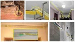
Despite such economies of scale, the fact that only 5% of all homes connected with fiber in the U.S. are MDUs speaks to the deployment challenges carriers face here and the need for innovative MDU cabling options. Space is at a premium and the aesthetics of new installations are a major consideration when dealing with building owners. Carriers also need low-cost, reliable cables that are fast to install.
Recent advances in fiber technology that offer significantly improved bend performance have brought the industry closer to its MDU goal: cable as fast and easy to install as copper that delivers the high performance expected of optical fiber.
Recognizing changes in fiber installation requirements, in late 2006 the ITU-T developed Recommendation G.657 to define and standardize two classes of singlemode fiber with different levels of bend performance:
• Recommendation G.657.A defines “bend-improved” fibers. These fibers are required to be backward compatible with standard low-water-peak singlemode fibers as specified in ITU-T G.652.D; the associated fiber design tradeoff limits the minimum bend radius specification to 10 mm. Bend-improved fibers have enabled major density improvements for FTTH hardware. They also enable a reduction in weight and size of local convergence cabinets by approximately 40% and 75%, respectively, when combined with improved fiber management.
• G.657.B-compliant fibers are called “bend-tolerant” fibers and not required to be backward compatible. This is a big tradeoff but enables a reduction in the specified minimum bend radius to 7.5 mm. However, this modest further reduction in minimum bend radius is not enough to enable fiber cable installation practices on par with copper installation in terms of speed, ruggedness, and flexibility or to enable further density improvements for fiber hardware.
Several “new” fiber products have been launched in the past two years based on one of the following well established fiber design options that are known to improve bend performance:
- Reducing the core diameter and/or increasing the refractive index of the core.
- Depressed cladding fibers where a circular zone around the core is doped (typically with fluorine) to achieve a lower refractive index than silica glass.
- Trench-assisted fibers similar to depressed clad fibers, but the ring of doped silica with a lower refractive index is further away from the core.
Since these enhancing options are incremental modifications of existing approaches to process and design, the achievable macrobend improvements are limited and only incremental as well.
Completely different approaches also have been developed, primarily hole-assisted fiber (HAF) and photonic band-gap fiber (PBGF). These fibers have very different waveguide profiles compared to the profiles of legacy fibers that leverage the technology of chemical-doped waveguide fabrication. While these HAF and PBGF designs produce very bend-insensitive fibers, they are very costly to make in large quantities and long lengths, difficult to connect, and not backward compatible with the aforementioned standards. In addition, HAF and PBGF fibers are not universally compatible with existing termination and field procedures.
Figure 1 shows the bend performance requirements of fibers in compliance with ITU-T recommendations G.652.D, G.657.A, and G.657.B and illustrates which fiber designs are capable of what bend performance.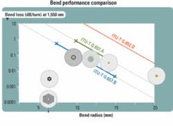
While providing excellent bend performance, the manufacturing and compatibility challenges of HAF and PBGF were considered too tough to overcome-until recently, when a nanostructure-based fiber technology was developed that enables bend radii specification down to 5 mm while enabling backward compatibility with industry standards and existing installation processes. Engineered nanoscale structures within the fiber create a bend-insensitive fiber with a unique “trapping” mechanism that confines the light in the core better than what is possible by changing the material composition of the glass by fluorine doping. It is totally synthetic and does not require any mechanical work on the glass during manufacturing.
To evaluate the new technology’s potential benefits, users must consider two major questions. First, what kind of performance do MDUs really require-i.e., how low does the bend radius have to be to achieve attractive deployment cost savings while maintaining an adequate power budget? Second, what mechanical reliability and field practices should installers consider?
The answer to the first question lies in an understanding of the application space. In many field trials and deployments with carriers across the globe, it has become evident that bend radii down to 5 mm are required to be on par with copper cable installation and to maximize the potential labor and material cost savings. Bending cables around corners at the building entrance; in hallways, wiring closets, and wall outlet boxes; and around doors or other obstacles is common practice in premises installations.
Photo 1 (front page) provides several examples of fiber-optic cable installation in MDUs. The drop cable routing shown in Photo 1 along the hallway required the cable to negotiate 15 bends to pass only four living units. In addition, sometimes a heavy mechanical load is induced where a well-intended effort to organize a bundle of cables results in a single cable carrying the burden of the whole bundle.
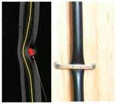
Meanwhile, stapling cables to studs, molding, and dry wall is common practice to accelerate the installation process and avoid the high material and installation cost of microducts. Photo 2 shows the effect on the optical fiber of stapling cable to studs. From these images, it is clear the bending induced by this practice definitely creates bend radii in the 5‑mm range.
It seems clear that to maximize the potential for lower deployment costs, faster rates of deployment, meeting optical power budgets, aesthetically acceptable cable designs, and optical capability at a bend radii of 5 mm will be required and specified. Discussions with carriers internationally indicate they understand and are comfortable with technology that meets this requirement. As an example, NTT has already deployed products with performance targeted at bend radii below 5 mm.
Naturally, when thinking about bends to these tight radii, customers can and should investigate the long-term mechanical considerations-part of our second question. Over the years, extensive investigation and modeling of optical fiber mechanical reliability have been performed. As a result, standard tests have been developed to ensure fibers meet the reliability requirements for optical networks. The two main test parameters are proof and dynamic tensile strength. It is important to note that mechanical reliability is a statistical parameter with a probability distribution.
Standard singlemode fibers have bend radii specifications to ensure virtually “zero breaks” over a 20-year period. The latest ITU-T G.657 standard for fibers with improved bend performance implies a level of “managed reliability” where modeled failure rates will slightly exceed “zero” over this lifetime.
The outer surface of a bent fiber is under stress just as if the fiber was under tensile load. The stress decreases with radial position, through a “neutral axis” along the center of the fiber, with the inner surface of the bend actually in compression (see Fig. 2). The likelihood of any fiber breaking depends on bending stress (i.e., bend radius), the length under bend (i.e., the number of bends), the strength distribution (i.e., length spacing between flaws that will be expected to break), and the fatigue (i.e., flaw growth) during service. As a result, the probability of fiber component failure for bends down to 5 mm in radius is still in the low single-digit parts per million. At these levels, the fiber is still the most reliable optical component in the network.
These modeling results can be extrapolated to a carrier’s network configuration to estimate the probability of a link failure per household, per kilometer of fiber deployed, or other relevant metrics.
Finally, what are the considerations in using this nanostructure-enabled technology in the field? Let’s walk through the three key processes required to connect an optical fiber when installing a link in the network and see what needs to be done.
1. Access the fiber in the cable and prepare for the splice. This step is the same for nanostructure-enabled fibers and standard fibers. A technician uses lint-free wipes to clean the optical fiber after entering the cable, accesses the right fiber, and mechanically removes the coating; sometimes a cleaning fluid (e.g., isopropanol) is used with the wipes. The technician then cleaves the fiber for an optimum fiber endface to achieve the desired splice loss with an automatic fusion splicer. If the fiber endface comes into contact with any material (dust, liquids, hands, surfaces, etc.) before the splice is completed, it should be cut back an appropriate length (typically 2 to 4 inches) and the cleaning and cleaving process must be repeated. If fibers have been cleaved and stored in terminals or wall outlets for future use, standard procedures require the installer to cut back, clean, and cleave again before connection.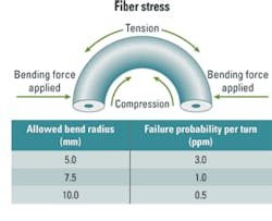
Field-installable connectors may be used as well. When the fiber is prepared properly and the connector assembled per the recommended procedures, the installer will see no difference between currently available fibers and nanostructure-enabled fibers. Both connectivity options achieve splice/insertion and return losses in the same range expected with standard singlemode fibers. In addition, nanostructure-enabled factory-terminated cables are available that can be used in a plug-and-play fashion. After testing thousands of connectors, the typical insertion loss for mating connectors with standard singlemode fiber and nanostructure-enabled fibers and nanostructure-based fibers with themselves is in the same range as today’s state-of-the-art connectors.
3. Testing. All bend-improved and bend-tolerant fibers create some challenges for test equipment makers since certain fiber parameters must be modified to achieve the bend performance (e.g., mode-field diameter, cut-off wavelength). Even if the fibers are standard compliant, there is always a window of performance that the test equipment operator has to take into account. When using an OTDR to test a link where fibers with different mode-field diameters are connected, “gainers” or “exaggerated loss” effects can be seen. These phenomena are well known, and operating procedures calling for testing the link from both ends and averaging the results when seeing these are already in place. In MDUs, where comparatively shorter lengths dominate, an alternative to bidirectional testing already is used for the drop section of FTTH networks. Testing the entire link with power meters is an easier and less costly technique and gives the true link-loss measurement. Finally, live fiber testers have demonstrated sufficient sensitivity to detect light in nanostructure-enabled fibers.
In summary, nanostructure technology enables cabled fiber to be bent very tightly with virtually no signal loss while still maintaining backward compatibility with industry standards and existing installation processes. The bend performance this new fiber achieves enables network planners to no longer worry about bend-induced link loss. Feedback from early adopters shows that by reinforcing existing operating procedures, network installers will see minimal impact on field termination and testing practices. They can now treat truly bend-insensitive optical fiber cable like copper cable-and provide the bandwidth they need today and tomorrow.
Bernhard Deutsch, PhD, is director, marketing and market development, at Corning Cable Systems (www.corningcable.com). David R. Velasquez is global product line manager, telecom and premises fibers, at Corning Optical Fiber (www.corning.com).

