Datacenter providers see future-proofed possibilities in co-packaged optics
By Martin Hempstead and Riley Freeland / Corning
What fiber and connectivity developments are required to bring CPO to market with optics invading the switch box?
The advent of co-packaged optics (CPO) has been long anticipated but is becoming increasingly desirable as data needs accelerate. As they continue to scale, data centers face substantial challenges, particularly in reducing power dissipation and cost per bit. CPO will play a significant role in helping to meet those challenges.
The companies and institutions working on CPO have made great strides in developing suitable electronic components. But hundreds of meters of fiber will be packed into the switch box for the first time, and faceplate connections will have unprecedented densities. As a result, the design and development of optical system solutions will also be critical elements in the success of CPO.
Optical components with performance tailored to the CPO application and effective solutions for managing the fiber in the switch box are vital in optimizing the complete optical system. Three aspects of CPO deployment, in particular, hinge on the properties of the fiber and the optical interfaces: optical power loss, the trade-off between minimizing bend loss and controlling for MPI and maintaining the polarization state if external lasers are used.
Why is Fiber Management Important?
In today’s data center switches, external fiber optic connections that carry data terminate on pluggable transceivers on the housing faceplate. The optical data stream is coupled to the electrical signals at that interface. (See Figure 1)
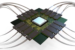
With a CPO realization of a 51.2 Tbps switch, the substrate connects a central regulator ASIC to 16 optoelectronic (O/E) tiles on the substrate perimeter. These tiles are connected to optical fiber signal cables that run to the switch box faceplate and receive power from external lasers that they modulate to produce the outgoing optical signal stream.
They communicate between the transceiver and the switch application-specific integrated circuit (ASIC) via copper traces on printed circuit boards. Under the CPO paradigm, as the optoelectronic conversion is pushed back from the faceplate to the switch substrate, long electrical traces are replaced with virtually loss-free optical fiber.
With CPO, the fiber path continues past a connector at the faceplate and into the switch box, ending at photonic integrated circuits (PICs) on optical tiles attached to the switch substrate. This shift presents the novel challenge of routing and connecting hundreds of optical fibers within a compact and crowded space, creating a need to minimize the footprint of the optics while still achieving performance and reliability targets.
Minimizing the optics footprint could mean routing fiber on the shortest path – consistent with the fiber properties – between the optical tile and its associated faceplate connector, but this would lead to at least eight different cable lengths for a 51.2 Tbps switch with 16 optical tiles and mirror symmetry. This proliferation of parts might be undesirable from a manufacturing point of view. If a reduced set of cable lengths were to be used, then the “constant length” routing would have to accommodate excess cable in some paths.
Fiber Layout – Bend Loss, MPI, and Reliability
With space inside the switch box at a premium, the risk of mechanical interference with other components should be reduced as much as possible. When building switch boxes containing hundreds of fibers, it will be essential to have them deployed predictably while minimizing trouble spots like crossings and avoiding issues such as cable buckling.
This management goal will be greatly facilitated by using tightly bent fiber to follow short paths between the faceplate and chip. With typical telecommunications-grade single-mode fiber, too much light may be lost at these bends, but we can mitigate this by using bend-insensitive fiber designs.
However, in using such designs, care will be required to control multipath interference (MPI).
Power can be coupled and propagated in more than one fiber mode at each optical interface in the switch box (e.g., connectors, FAUs). Given the short fiber lengths likely to be used in CPO, power in higher-order modes (HOMs) will not be extinguished before the following interface, where the multiple modes will interfere with each other – the phenomenon known as MPI – ultimately causing wavelength-dependent power at the detector. At some wavelengths, that power reduction could be up to twice in decibels, arising from the independent losses at each interface.
Thus, unmitigated MPI could complicate some benefits of using fiber with low bend-loss. For these systems, a bend-insensitive fiber that also suppresses MPI in very short fiber lengths would need to be designed. One potential approach is to reduce the fiber cut-off wavelength to increase HOM loss substantially.
Even if MPI is reduced to insignificance, the coupling losses at those interfaces matter, too. The redesigned bend-insensitive fiber must maintain low coupling loss to Corning® SMF-28® Ultra or other fiber used in the data center to connect switches. This imposes constraints on the mode-field diameter of the CPO signal fiber.
To permit practical, low-cost provisioning of the switch box optical cables, the fiber management approach must include some means to accommodate length variations introduced by the cable manufacturing process. One strategy is to tie down the cable at points along its path and allow it to take a relatively unconstrained path between these tie-down points. The smaller the radius of curvature of that path, the less a bundle of cables will spread out for a given length variation.
An alternative is to provide specific accumulator structures to contain excess cable length. To keep such structures unobtrusive, the fiber should tolerate deployment in very tight loops, as small as 10-mm in diameter, retaining its low-bend loss and high reliability. These attributes are required of fiber that lends itself to “shortest path” and “constant length” routing.
Switch integrators can achieve a reliable, clean build using optical cable management hardware and layouts following the design rules enabled by fiber optimized for CPO.
The PMF Path
In some CPO implementations, external laser power is brought to the PIC along the polarization-maintaining fiber (PMF) to maintain the polarization extinction ratio (PER – a measure of polarization state purity) and align it to the correct polarization mode of the PIC waveguides.
Meeting the power budget for CPO connections entails managing insertion loss (IL) from the laser source to the detector through PMF and signal fibers. The PMF will ideally have the same design rules as the signal fiber, so bend-insensitive PMF is also desirable.
In addition to the constraints it shares with the signal fibers, the PMF must resist PER degradation even in tightly bent configurations. To facilitate its deployment in the switch box and management of the polarization state from the laser to the O/E chip, the PMF fiber should be ribbonized to maintain its orientation.
The PMF will also carry high optical powers, perhaps hundreds of milliwatts, so attention must be paid to the reliability risks associated with spilling significant power into connectors or coatings.
Optical Interfaces
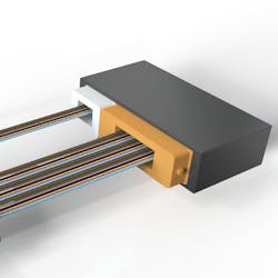
With ribbons connecting to the O/E tile on the perimeter of the ASIC substrate, a small FAU (gray housing) brings laser power via a PMF ribbon to the chip, while an SMF ribbon carrying signals is attached with a separate, larger FAU (orange housing). (Figure 2)
Like optical fiber, the fiber array unit (FAU) is a component that may slip under the radar because of industry familiarity with its use for pluggable optics. However, the CPO application places greater demands on an FAU’s performance.
FAUs bring fibers to a row of fibers or other waveguides, such as those on a PIC, transporting light across the interface by aligning the waveguides to the correct fibers. Transverse misalignments of even a fraction of a micron can cause appreciable optical power loss. Achieving very low coupling losses demands tight positional tolerances and fibers with well-centered cores.
In pluggable optics, low-fiber counts such as two or eight fibers are typically used in FAUs. With CPO, higher densities necessitate higher-fiber-count FAUs, with 32 or even 64 fibers, for example.
The FAU manufacturing process also needs to accommodate the PMF in systems that use it, orienting the polarization state to match the state required by the PIC and maintaining the PER.
Much bare fiber is handled in assembling FAUs, so the process must be designed to retain the high intrinsic reliability of the fiber.
Fortunately, there is precedent for the kind of FAUs we’ll need in CPO. More complex FAUs are already being made for telecommunications providers. These users need higher channel counts and better reliability than pluggable optics applications. CPO resembles these telecom applications, so those few suppliers with experience manufacturing FAUs for telecom settings have a real advantage, particularly if they are vertically integrated, by engineering the fibers themselves.
The fibers and FAU can be designed and specified to maximize compatibility and optimize performance
Many of the exact requirements to handle high-fiber density and PMF (where it’s used) apply to other optical components.
With over 1,000 signal fibers for a 51.2 Tbps switch using the DR4 scheme, fitting them into a 1RU format requires high-density multifiber connectors; US Conec MMC and MXC™ formats are examples of connectors that allow very high-fiber densities.
Connectors must be low-loss to support the power budget.
Suppose external laser small-form-factor pluggables (ELSFPs) are used. In that case, there may be blind-mating laser modules with electrical contacts and optical connectors with oriented PMF to preserve the polarization state across the connector. The PMF connectors closest to the laser must handle high-power densities without damage and tolerate heating and other effects that may arise from stray light. This is particularly challenging since the connector end faces are exposed to foreign contaminants; expanded beam connectors allow a significant reduction in power density and may play a role in enabling reliable connections.
Optics in CPO Systems
CPO will soon be a reality that relies on a system of complex, interconnected components working well together. For optimum overall performance, these components must be designed with the specific requirements of CPO in mind, which for the optical subsystem include efficient and unobtrusive deployment within a crowded switch box, low power losses, absence of MPI impairments, and good reliability. Some CPO realizations also need optical polarization state control.
The familiar fiber and connectivity products, while having impressive attributes, are not optimum for the CPO application, and there is great scope for enhancing the performance of the optics by moving beyond default solutions to those specifically designed for the role.
Martin Hempstead is the telecom product development manager for D-COF glass development at Corning.
For related articles, visit the Data Center Topic Center.
For more information on high-speed transmission systems and suppliers, visit the Lightwave Buyer’s Guide.
To stay abreast of fiber network deployments, subscribe to Lightwave’s Service Providers and Datacom/Data Center newsletters.


