The critical role of electronic dispersion compensation in SFP+ applications
by Ahmet Balcioglu, PhD
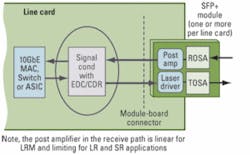
OVERVIEWSFP+ channels are significantly more challenging than those of X2 and XFP LRM modules. To achieve performance margins similar to X2 and XFP modules, SFP+ LRM modules require pre-emphasized linear receiver and off-module EDC technology with 300-m capability.Standards-based optical modules for 10-Gbps applications have evolved within the last decade from the 300-pin multisource agreement (MSA) to XENPAK, XPAK, X2, XFP, and now to the small form factor pluggable SFP+ module. The SFP+ form factor enables high-port-density designs by removing the requirement for an on-module retimer. Instead, the retimer is moved to the host line card where it can be combined with other ASICs, such as in an integrated clock and data recovery (CDR) unit with electronic dispersion compensation (EDC), as illustrated in Figure 1. The separation between the SFP+ module and the host line-card devices in the receiver path, however, places more stringent requirements on EDC performance to compensate for additional electrical signal impairments through the physical module-board connection and extended path length.
Media access controllers (MACs) and switches with 10-Gbps CDR functionality are now available. The integration of high-speed serial I/O into such ASICs simplifies the pin count and reduces the cost of mating components. Depending upon the host line-card design and layout, the extended path through the printed circuit board (PCB) may exceed as much as 8 inches of FR4, yet still needs to comply with the SFF-8431 industry standard that defines the electrical specifications of SFP+ SR, LR, and LRM modules; direct-attach cables; and host. Since the 10-Gbps I/Os of these large devices may not be sufficient to guarantee compliance to the specifications, a signal conditioner must be used to bridge the SFP+ modules with the host ASICs.This paper discusses some of the technical challenges involved in developing an SFP+ module-based system for 10-Gigabit Ethernet (10GbE) LRM, SR, and LR applications and the key factors designers should consider to achieve the link margins required for practical system deployment. The information provided is based on actual measurements made on an SFP+ evaluation system.
SFP+ modules are designed to support 10GbE data communication in short-reach (SR), long-reach (LR), long-reach multimode fiber (LRM), and direct-attach copper cable applications. SFP+ modules for SR and LR applications are based on a limiting receive path, whereas modules for LRM and direct-attach copper cables are based on a linear-mode receive path. SFP+ LRM modules must equalize the modal dispersion encountered over 220 m of FDDI-grade multimode fiber (MMF)—with coverage of up to 99% of the deployed fiber of this type—per IEEE 802.3aq 10GBase-LRM. They also must overcome signal losses and reflections due to SFP+ connector and copper trace runs of up to 8 inches of FR4.
A CDR device with advanced EDC can meet these requirements. The EDC can be implemented using various equalization techniques. Feed-forward equalization paired with decision-feedback equalization (FFE/DFE) and maximum likelihood sequence estimation (MLSE) are the most common of these methods.LRM stressors and characteristics
An SFP+ evaluation board has been designed to characterize LRM stressors (pre-, post-, and symmetrical) as defined by the IEEE 802.3aq standard. The LRM stressors represent the characteristics encountered over a minimum of 220 m of low-grade MMF.
Among the LRM stressors, the split symmetrical stressor is the toughest, since the main energy is split between two cursors. Meeting the split symmetrical stressor requirement demands a robust EDC design architecture. The SFP+ evaluation board channel characteristics relating to the forward and reflected signal components (i.e., the SD11 and SD21 parameters) for 2-, 4-, and 8-inch stripline traces can be found in Reference 1.
A linear ROSA with a pre-emphasis of 3.4 dB was used in the evaluation board fixture to convert the optical signal to the electrical domain. The waveform dispersion penalty (WDP) and impulse response of LRM stressors were measured. The pre-, post-, and symmetrical stressors, compliant to the IEEE 802.3aq specifications and characterized in the optical domain, were generated by a Circadiant Hydra Stress Generator. For tests performed in the electrical domain, signal calibration was performed up to the input of the module compliance board.
Table 1 shows the measured WDP and calculated delta WDP for symmetrical stressors in the optical and electrical domains. As the table illustrates, the distortion due to the SFP+ connector and FR4 run length is defined by delta WDP (dWDP), which represents the difference between WDP measured at the point of interest and the calibration test point.
The WDP data indicates that the signal distortion is mainly due to the SFP+ connector, which degrades the measurement by more than 0.5 dB. The distortion due to the FR4 run length is also roughly 0.5 dB. As shown, the distortion in the optical domain is reduced by pre-emphasizing the linear transimpedance amplifier (TIA) output, which causes negative distortion before the module compliance board (back to back—B2B). Linear receivers without pre-emphasis will result in increased distortion relative to the ideal passive electrical WDP values shown in Table 1.
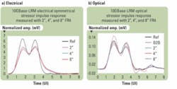
In addition to analyzing the WDP data, the impulse response should be considered. As shown in Figure 2, the SFP+ connector and the stripline copper traces of the FR4 PCB significantly degrade the channel impulse response. As depicted in Figure 2a, the single bit of the split symmetrical stressor spreads by more than five bit times in the electrical case while the pulse spread in the optical case, shown in Figure 2b, is not significant. In addition, the shape of the impulse response is relatively unchanged in the optical case whereas it changes considerably in the electrical case.
As shown in both optical and electrical cases, the impact of the FR4 traces on the impulse response is not as significant as the influence of the SFP+ connector. The impact of pre-emphasis is apparent between 4 and 6 UI, while the reflections between 6 and 7 UI are thought to be from the linear ROSA fixture.
As illustrated, the WDP increases considerably and the single data bit spreads beyond the specifications, thus requiring an EDC technology that can equalize stressors beyond 220 m and up to 300 m of FDDI-grade MMF. An improvement of the SFP+ connector and minimizing its impact by pre-emphasizing the linear module receiver output via an advanced EDC technology are required to ensure a reliable optical link that is suitable for practical system deployments.
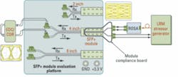
Optical modulation amplitude (OMA) sensitivity is a common way to express the optical link performance. The OMA sensitivity of LRM stressors was measured with a pre-emphasized linear receiver in B2B, 2-, 4-, and 8-inch FR4 SFI channels. A block diagram of the typical SFP+ LRM module test setup is shown in Figure 3.
A typical bit-error rate (BER) versus OMA plot of a symmetrical stressor measured with a worst-case SFI channel is given in Figure 4a. Figure 4b depicts the OMA sensitivity versus WDP of a split symmetrical stressor at a BER of 1.0E-12 as a function of B2B, 2, 4, and 8 inches of FR4. It is interesting to note that the OMA degradation versus WDP of the channel is linear, indicating that the EDC partially compensated the distortion. Although the EDC was not able to entirely compensate for the channel impairments of the interface, the OMA sensitivity measured with the worst channel characteristics is well within OMA sensitivity requirements. It is evident from Figure 4b that the performance margins of a worst-case SFP+ channel are less than those of X2 and XFP LRM modules by at least 1.0 dB.SFP+ channel characteristics are significantly different and more challenging than the X2 and XFP LRM module environments because of additional WDP distortion and pulse spreading due the additional connector and FR4 traces. Although pre-emphasizing the linear module output reduces WDP distortions and pulse spreading, it does not compensate entirely for them. Adaptive firmware optimization becomes essential in dealing with the remaining WDP and pulse spreading effects.
One of the key requirements of system designers in limiting SFP+ SR and LR module applications is that the presence of EDC must not degrade the link performance. The characteristics of SFP+ SR and LR modules vary considerably among various modules and require an adaptive equalizer to correct. It is also evident from the multivendor interoperability testing of SFP+ SR and LR module applications that the combination of transmitter and receiver might exceed SFF-8431 specifications and degrade the link performance and cause BER failures.2In short, testing has determined that the use of EDC with an autonomous adaptive algorithm in limiting SR and LR module applications ensures a stable and reliable link without user intervention by compensating for the distortions and reflections due to the SFP+ connector and copper losses. Using the autonomous adaptive functionality of EDC circuitry also assures a reliable link over large vendor-to-vendor module variations.
SFP+ channel characteristics that cover a worst-case, real-world system environment were studied, which revealed that SFP+ channels are significantly different and more challenging than those of the X2 and XFP LRM form factors. The primary limitation of the SFP+ link is the connector.
Pre-emphasizing the TIA output reduces the impact of the connector by decreasing the WDP and the spread of the impulse response of the LRM stressors. In addition to an improved SFP+ connector and pre-emphasized linear receiver output, an advanced EDC technology with 300-m capability is essential in equalizing 220-m LRM stressors and compensating for the SFP+ module connector along with PCB stripline copper trace losses. The EDC technology is the key to ensuring the performance margins needed to enable SFP+ SR, LR, and LRM modules in practical 10GbE switch and router applications.
- A. Balcioglu, “Performance Margin Considerations for SFP+ Transceivers,” Optical Fiber Communications/National Fiber Optic Engineers Conference, 2008.
- M. Mazzini and S. Schube, “SFP+ Interoperability Demonstration White Paper,” http://www.ethernetalliance.org/images/SFP%20White%20Paper1.pdf
SFF-8431 Rev3.1: Enhanced 8.5 and 10 Gigabit Small Form Factor Pluggable Module “SFP+”
ftp://ftp.seagate.com/sff/SFF-8431.PDF
IEEE 802.3aq: 10GBase-LRM
http://www.ieee802.org/3/aq/index.html
Lightwave Online: Ethernet Alliance Forms SFP+/EDC Subcommittee
http://lw.pennnet.com/display_article/321011/13/ARCHI/none/NNEWS/1/Ethernet-Alliance-forms-SFP+/EDC-subcommittee/
Ahmet Balcioglu, PhD is a senior applications engineer at Vitesse Semiconductor Corp. (www.vitesse.com).


