Time to test optical switch's voltage controller reduced from three days to two hours
By GEORGE ATHERTON
Microstar Laboratories
The voltage controller used in an optical switch presents an enormous testing challenge because it can incorporate as many as 2,520 discrete channels that each must be tested separately. In the past, it took an operator about 30 seconds to test each channel manually with a voltmeter, which overall added up to about three days. Recently, a test system reduced that test time to about two hours.
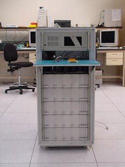
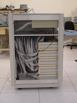
The new test system plugs into the power supply and simultaneously tests each channel in a total cycle time of about two minutes. It's based on a standard rack-mounted computer with five data acquisition cards each connected to eight 64-channel multiplexers. Key to the application's success is the data acquisition cards' ability to handle 800,000 samples per second, making it possible to take ten samples from each channel in just a few seconds.
The ability to apply a precise voltage to each of the mirrors at the heart of all-optical switches is a critical test issue for system manufacturers. One company's switch uses 630 mirrors that can each turn on two different axes. The result is that four discrete voltage sources are required for each mirror, to turn each mirror in the positive and negative direction on each axis.
This same system manufacturer purchased a voltage controller with 2,520 discrete channels to control the mirror array. The voltage controller delivers up to 160 volts and about 100 microamps per channel. To ensure reliable performance, the system manufacturer needs to test each of these channels before the crossconnect is assembled.
This type of testing used to involve a tedious manual process in which an operator connected a voltmeter to each channel and performed a series of tests. While it took less than a minute to test each channel, the large number of channels meant that three days were required to complete the testing. This lengthy process is a key bottleneck in ramping up production of the units to meet telecommunications demand.
What is needed is a device that tests simultaneous channels. The biggest challenge the technicians faced in designing this type of testing system was sampling all of the channels within a short period of time. One option they considered was multiplexing a single-channel data acquisition system out to 64 channels. But the data acquisition device only has one measurement input so it would have to switch one channel at a time, make the measurement and store the results, which would take 30 seconds per channel or a total of about 21 hours to scan all of the channels. That's nearly as long as it takes to do the job by hand. Another problem is that testing a single unit would require 40 devices--about $85,000 in data acquisition hardware including the multiplexers.
Designing a rack-mounted solution
Instead the technicians built a rack-mounted computer with a peripheral component interconnect (PCI) bus that can handle less expensive off-the-shelf data acquisition cards. But the technicians faced a challenge because the conventional data acquisition cards aren't able to handle the amount of throughput that they needed to push through in order to meet the cycle time bogey. Then they discovered a data acquisition card with onboard intelligence designed especially for high speed simultaneous processing. The technicians developed a configuration in which five of the cards are mounted on the PCI bus with each card connected to eight 64-channel multiplexer cards. With its high data rate, each data card can scan the 512 channels in a couple of seconds. It takes another 15 seconds to download the data to the host PC. The elapsed time for the entire operation is only about two minutes. Of course, the operator still needs to connect the cables and perform other tasks, but the resulting two-hour cycle time is a dramatic reduction from using manual or other automated methods. The total hardware costs, including data acquisition processor boards, multiplexers, and cables are about $46,000.
The onboard microprocessor runs an operating system optimized for high-performance real-time data acquisition and control applications. This intelligence extends the power of the Windows user interface by executing all processor-intensive routines in real time and by performing data reduction so that the software on the PC can handle more demanding applications than usual. There's never any danger of losing data regardless of how many computer cycles are dedicated to the foreground application or even if Windows crashes. The test engineers were able to develop a powerful front end and data analysis application without worrying about the ability of Windows to service the real-time application.
It took the engineers only a few days to write and test the commands required to measure each channel 10 times and send the results to the host PC. This program interfaces with the test executive operator interface, which runs on the PC under Windows 98. The operator interface was written using a National Instruments Lab Windows/C language virtual instrument test development system. The interface leads the operator through the entire testing process.
First the operator sets the device under test on a shelf of the rack that contains a bar code scanner and then connects the multiplexers' cables to the unit. After this, the operator hits a start button and the test executive automatically scans the serial number of the unit and selects the right tests for that model. The first iteration of the tester measures all channels at full voltages. The vast amount of data collected is written directly to a database for subsequent review and analysis. A future upgrade is planned to measure four different voltage levels: 40, 80, 120 and 160 volts.
George Atherton is vice president of Microstar Laboratories (Bellevue, WA). For further information contact Microstar Laboratories via its Web site at www.mstarlabs.com.
