Negative dispersion fibers increase signal distances up to 300 km
The effects of transient and adiabatic characteristics maintain satisfactory laser performance independently of laser chirp.
ARMEN SEVIAN, PASCAL DUPRIEZ, AND DAVID CULVERHOUSE, Corning Inc.
To date, the application of DWDM has been most dominant in long-haul and high-data-rate applications. The capability of an optical fiber to support multiple wavelengths, cost-effectively addressing the exponential growth in bandwidth demand, has been most prevalent in these systems. The last two years, however, have since marked the introduction of DWDM in metropolitan-based networks, where legacy systems have traditionally operated with a single wavelength capability in the 1,310-nm window using standard singlemode fibers.
As the demand for bandwidth begins to migrate from the long haul into the regional market, specific interoffice and local-area-network challenges need to be addressed. In contrast to long-haul systems, which in a very broad sense can be described as point-to-point links ranging from 300 km to 2,000 km in length, metropolitan-based networks lend themselves more readily to architectures based on interconnecting rings. These architectures encompass the regional, interoffice, and access segments of the network and incorporate spans ranging from 50 km to distances of up to 300 km in length. Added to this, metro networks can be differentiated from long-haul applications by the sheer volume of components (i.e. receivers, transmitters, and multiplexers), which means that cost is paramount in these networks.The cost advantage of directly modulated lasers compared to externally modulated sources is one reason why these lasers are ideally suited to metropolitan architectures. Their main drawback, however, is that they are typically dispersion limited to distances of 100 km or less. This limitation is attributed to the interaction of a positive chirp with the positive dispersion characterizing standard fibers, which compounds the pulse broadening of the signal as it propagates along the fiber length. Therefore, in networks characterized by multiple path lengths, directly modulated lasers are confined to worst-case scenarios of about 100 km. But with the application of a negative dispersion fiber such as Corning Inc.'s MetroCor, distances can be extended to spans exceeding 300 km in length.
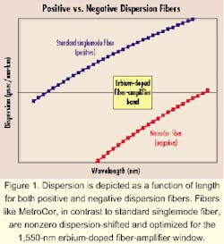
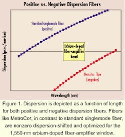
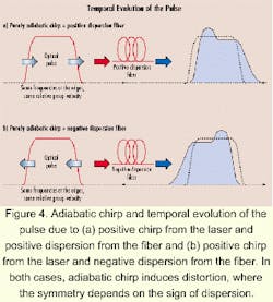
In long-haul applications and for data rates of 10 Gbits/sec and higher, externally modulated lasers based on lithium niobate are often the lasers of choice. However, in metropolitan-based networks, bandwidth and capacity requirements are likely to be adequately satisfied by data rates of 2.5 Gbits/sec. In addition, the cost advantages that directly modulated lasers provide are well suited to these architectures.One of the most important characteristics of a directly modulated laser is its intrinsic chirp. Depending on parameters such as geometry and material (enhancement factor, cavity properties, dielectric constant, carrier dynamics, etc.), these lasers fall into one of three main categories: transient-dominated chirp, adiabatic-dominated chirp, or combinations of the two. Depending on the characteristic of the laser, the laser will lead to different kinds of frequency shift within the pulse as the signal propagates along the fiber length.1 In the case of positive dispersion fibers, this can lead to severe degradation and variation in system performance (see Figure 1).
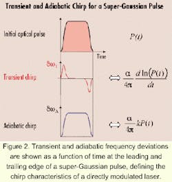
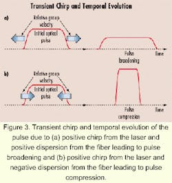
When using standard singlemode fiber (SSMF) and directly modulated lasers, transmission distances are typically not screened for lengths greater than 100 km. For a negative dispersion-shifted fiber, however, the interaction of the positive chirp characterizing the laser compensates for the negative dispersion of the fiber, enabling signals to exceed 300 km before dispersion begins to impact system performance.The transient and adiabatic characteristics of the laser are determined by the spectral components at the leading and trailing edge of the pulse (see Figure 2). For a transient chirp, the frequency components at the leading and trailing edge are of opposite sign, and therefore, lead to broadening or compression, depending on the fiber type (see Figure 3).
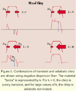
For a positive dispersion fiber, pulse broadening takes place due to the spectral components at the leading edge moving faster than the components at the trailing edge. In the case of a negative dispersion fiber, components at the leading and trailing edge act in the opposite sense, implying that the components move toward one another, which subsequently leads to pulse compression. Compression will continue to dominate until a point of maximum compression is reached, at which point a change in sign of the chirp will subsequently lead to pulse broadening. The significance of the initial pulse compression differentiates positive and negative dispersion fibers.In the equation, Δn is the frequency shift called chirp, P(t) is the intensity of the optical pulse, and Henry's alpha factor and k is related to the distributed-feedback-laser material and design parameters. The significance of increasing k is clearly illustrated in Figure 5, which describes the interaction that takes place when increasing the adiabatic component for the case of a negative dispersion fiber.
A pure transient chirp-dominated scenario is given by k = 0 and leads to pulse compression as previously defined. As k is increased, the result is an increased frequency offset in the central region of the spectrum. Subsequently, the components contributing to compression (or otherwise broadening in the case of positive dispersion fibers) are reduced at the leading and trailing edges.
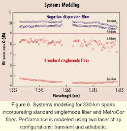
It is interesting to note the dynamics of the pulse as k is increased. The group velocity of the remaining transient components at the leading edge is increased, and the group velocity of the transient components at the trailing edge is reduced. This is clearly illustrated for the case k = 40. However, the spectral content of the edges is considerably reduced, and only a few components contribute to the pulse dynamics, therefore approaching to the case of zero chirp with frequency offset. This offset is represented by the color of the central part of the pulse.Figure 6 illustrates the results obtained from systems modeling for both adiabatic and transiently chirped directly modulated lasers at 2.5 Gbits/sec. The transmission distance modeled was 330 km and performance was monitored for both positive (or SSMF) and negative (MetroCor) dispersion fibers. The system performance was monitored in terms of Q (dB) which can be defined in terms of bit-error rate. A system Q of 9 dB corresponds to a bit-error rate of 10-15 and defines acceptable performance. A system Q of less than 9 dB typically results in eye-closure penalties.
In Figure 6, as the transient component is increased, the Q defining the system performance deteriorates. For a purely adiabatic chirp, the worst-case Q is 7.5 dB, and for a purely transient chirp, the worst-case Q is 4.5 dB. This means that as the transient component increases, the performance of the directly modulated laser will be dispersion limited at a shorter distance. Distances exceeding the dispersion limit will result in errors and degraded system performance.
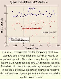
In fact, simulations modeling a laser characterized by a positive chirp show that performance will be dispersion limited at a distance of about 100 km. In the case of a negative-dispersion fiber, however, satisfactory performance is always maintained independent of the laser chirp. At the National Fiber-Optic Engineering Conference held in Denver, Corning and Nortel Networks (Ontario) jointly demonstrated distances exceeding 400 km using Nortel's OPTera Metro and Corning's MetroCor fiber.The experimental result demonstrating the impact of the transient and adiabatic chirp characteristics of a directly modulated laser is shown in Figure 7. The result measures the performance of commercially available lasers on 300-km fiber lengths incorporating either SSMF or MetroCor fiber. The experiment was uses 32 wavelengths operating at 2.5 Gbits/sec in the conventional band (1,530 nm to 1,565 nm) of the EDFA window.
It is important to note the transmitters used in this study were supplied by different manufacturers. But even for lasers supplied by the same manufacturer, extremes in performance were observed. This random performance can be attributed to the adiabatic and/or transient contributions characterizing each laser. In Figure 7, as was the case for Figure 6, acceptable performance was defined for Q values greater than 9 dB. For values less than 9 dB, eye-closure penalties led to degraded system performance. Those lasers resulting in a lower Q value when measured using SSMF were subsequently found to be dispersion limited at a shorter distance and characterized by transient chirp. In the case of a negative dispersion fiber, error-free performance was always maintained.
The use of directly modulated lasers with SSMF will mean system performance will likely be dispersion limited at distances not much greater than 100 km. Due to the contributions from both the adiabatic and transient components, the exact behavior characterizing the directly modulated laser is difficult to control during manufacturing. This means these lasers demonstrate extremes in their performance when using standard positive dispersion fibers.
The main advantage of a directly modulated laser compared to an externally modulated source is price, but operation to date has been limited to spans less than 100 km in length because of their dispersion limitations. In metropolitan-based networks and architectures based on interconnecting rings, incorporating dispersion-compensation techniques significantly adds to network complexity. However, with the application of a negative dispersion fiber, these networks are no longer liable to the same limitations of standard fibers. Instead, a negative dispersion fiber increases the uncompensated reach of directly modulated sources to distances exceeding 400 km, providing a more cost-effective solution in these networks.
- G. P. Agrawal, Nonlinear fiber optics, New York: Academic Press, 1989.
- I. Tomkos, et al., "Enhancing the performance of directly-modulated lasers systems using negative dispersion fibers for metro applications," NFOEC 2000.
Armen Sevian and Pascal Dupriez are senior market development engineers and David Culverhouse is the market development and engineering manager at the Metropolitan Fibers Div. of Corning Inc. (Corning, NY).
